
Vertical mixing bioreactor and drive system therefor

Inactive Publication Date: 2015-06-25
PBS BIOTECH INC
View PDF4 Cites 4 Cited by
  • Summary
  • Abstract
  • Description
  • Claims
  • Application Information

AI Technical Summary

Benefits of technology

The patent describes an improved bioreactor system that overcomes previous limitations. The system includes an impeller wheel with blades that create a tangential flow of fluid in the vertical plane and internal vanes that create axial mixing in the horizontal plane, resulting in a strong sweeping liquid flow that prevents particle settling and avoids gradients. The system also has a rounded bottom with a smooth surface that matches the curved shape of the impeller wheel, further preventing particle settling. The impeller wheel is fixed to the axle and inside wall of the vessel, ensuring full containment and sterility of the vessel. Overall, this system allows for better mixing of fluids and cells, and prevents particle settling, which can improve the efficiency and quality of biological processes.

Problems solved by technology

Manufacturing facilities with conventional stainless bioreactors, however, face numerous problems such as large capital investments for construction, high maintenance costs, long lead times, and inflexibilities for changes in manufacturing schedules and production capacities.
Such bioreactors can only be reused for the next batch of biological agents after cleaning and sterilization of the vessel.
These procedures require a significant amount of time and resources, especially to monitor and to validate each cleaning step prior to reuse for production of biopharmaceutical products.
However, scaling up to commercial manufacturing becomes operationally and economically unfeasible, as it would require thousands of plates.
Stainless steel bioreactors have been the standard platform for decades in the therapeutic protein sector but have several disadvantages such as laborious sterilization steps between batches, high capital and operational costs, long-lead times to install, and large space and infrastructure requirements.
Furthermore, their propeller-style impellers need to spin very quickly to mix larger volumes of liquid, resulting in increased levels of shear stress on suspended cells.
The ability of anchorage-dependent cells to attach to microcarriers is presumably hindered by shear stress, which can negatively impact cell viability and result in lower product yield.
However, these first generation single-use bioreactors mimic the impeller-based mixing style of stainless steel, resulting in similar issues with shear stress.
Thus the majority of currently available stirred-type bioreactors have increasing levels of shear stress as volume increases, which means that small-scale models are not representative of larger culture environments.
This poses serious challenges in their ability to be a low shear 3D platform for development of cell culture processes for the emerging cell therapy and vaccine & gene therapy markets.
The tall and narrow vessel design makes it difficult to eliminate gradients of kinetic energy dissipation within the vessel and ensure uniformly suspended solid particles such as cells and micro-carrier beads.
The designs thus have limitations to achieve fast, efficient, and homogeneous fluid mixing.
Problems with single-use bioreactor systems include particle settling due to the often uneven fit of heat-sealed bags on the vertical cylinder housing bottom, as well as particles becoming embedded in seams along heat sealed edges of the bag that define crevices.
However, the challenges to achieve efficient vertical mixing and homogeneous suspension of micro-carrier beads or cell clumps by using a horizontal impeller in a cylindrical shaped single-use bioreactor without baffles is only worsened with this design due to the low position of the impeller, not to mention the higher likelihood of the micro-carrier beads or cell clumps become embedded into the crevices between the impeller wheel and vessel bottom, which may cause them to be ground into small particles.

Method used


Image

  • Vertical mixing bioreactor and drive system therefor
  • Vertical mixing bioreactor and drive system therefor
  • Vertical mixing bioreactor and drive system therefor

Examples


Embodiment Construction

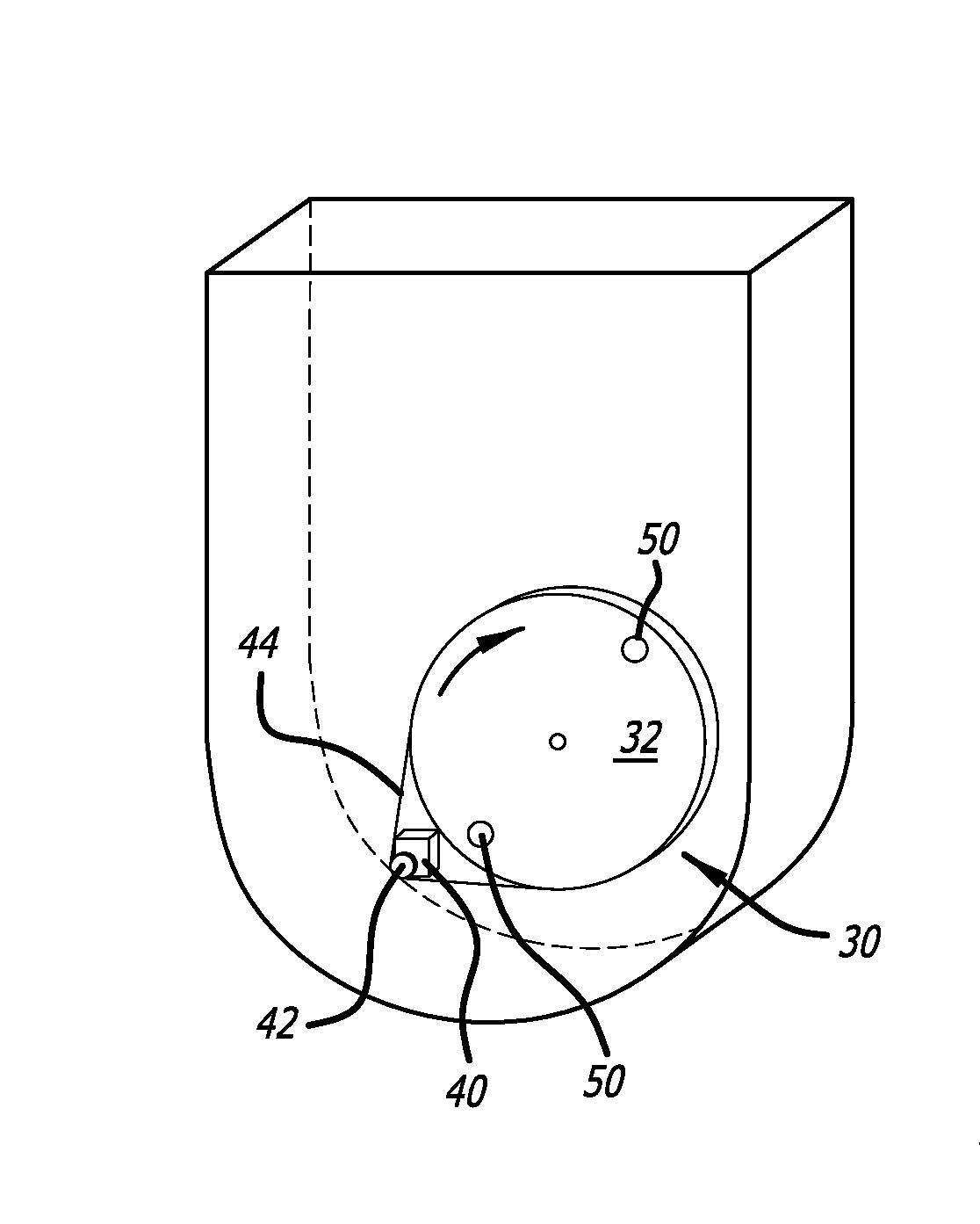
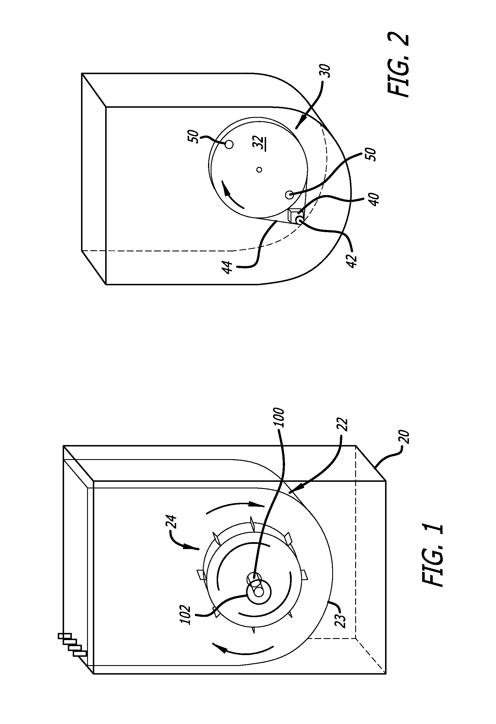
[0028]The present application provides a solution for driving bioreactor impellers that reduces contamination and maintenance. The solution involves an indirect drive system and modified impeller. In this context, “indirect” means that the impeller is driven via means other than directly rotating it through a shaft, for example. This eliminates the contamination issue with shaft seals and the like. However, pneumatic drive systems, such as disclosed in U.S. Patent Publication No. 2011 / 0003366 to Zeikus, are not considered indirect even though there is no shaft because of the introduction of air into the bioreactor vessel to rotate the impeller. Indirect thus means influencing the impeller completely from outside of the vessel.

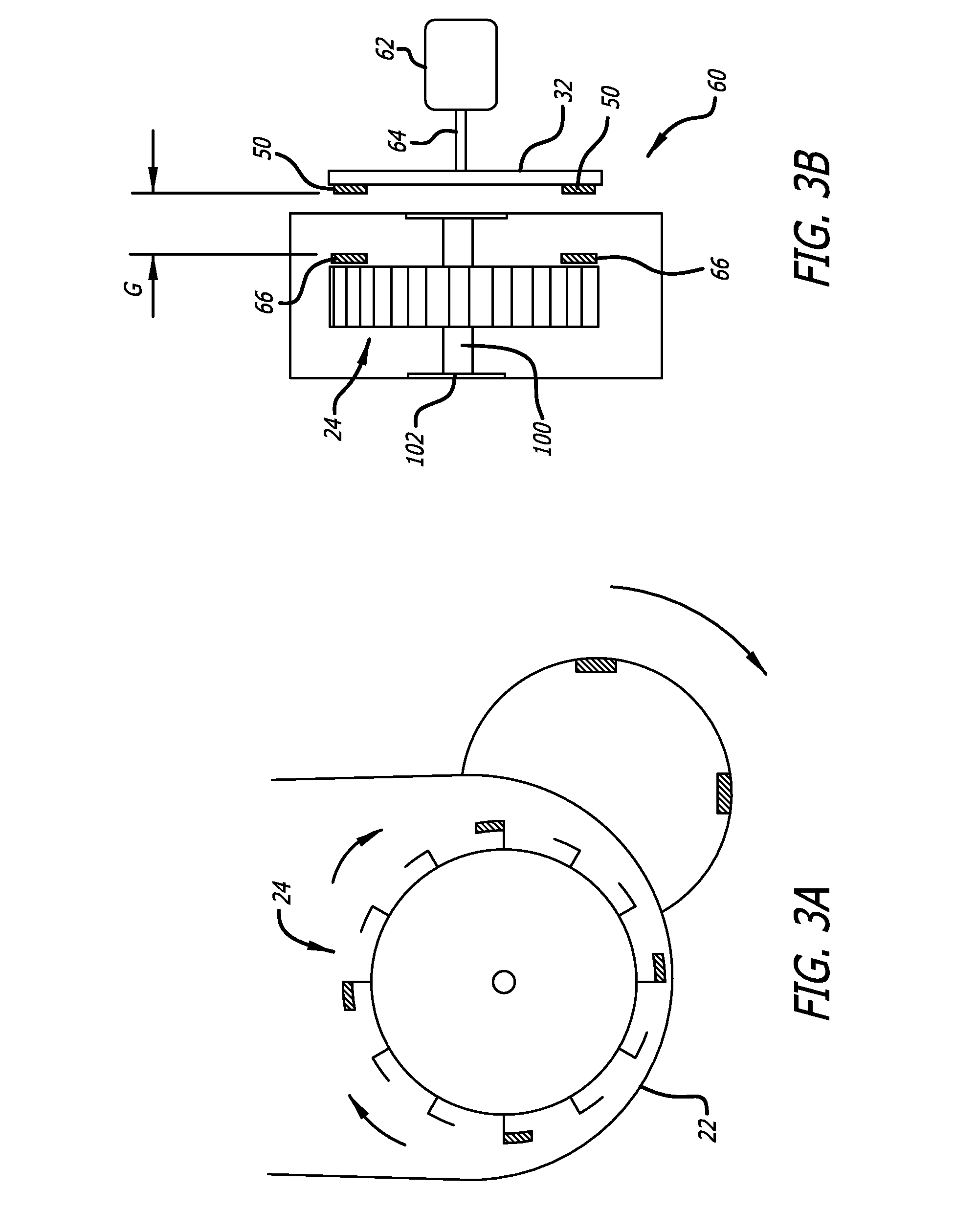
[0029]A bioreactor 20 illustrated in FIG. 1 includes a rigid outer container 20 that receives a single-use bioreactor vessel 22 of sufficient size to contain a fluid to be mixed. A variety of different sizes of bioreactors are used from the maximum working volu...


PUM


Abstract

A bioreactor includes a vessel containing a fluid to be mixed and at least one mixing device driven by a non-contaminating, indirect drive system. The mixing speed of the mixing device inside of the bioreactor may be controlled by the rotating speed of the magnets or the frequency of polarity changes of electromagnets outside the vessel acting upon magnets or ferrous material in or on the impeller wheel. The impeller wheel has a plurality of radially-oriented outer paddles with gaps therebetween that mixes fluid and culture cells around the vessel. A pair of curved axial flow vanes toward the middle of the impeller wheel washes the culture mix further.

Description

RELATED APPLICATION INFORMATION[0001]This patent claims priority from the following provisional patent applications: Provisional Patent Application No. 61 / 919,596, entitled VERTICAL MIXING BIOREACTOR AND DRIVE SYSTEM THEREFOR, filed Dec. 20, 2013.NOTICE OF COPYRIGHTS AND TRADE DRESS[0002]A portion of the disclosure of this patent document contains material which is subject to copyright protection. This patent document may show and / or describe matter which is or may become trade dress of the owner. The copyright and trade dress owner has no objection to the facsimile reproduction by anyone of the patent disclosure as it appears in the Patent and Trademark Office patent files or records, but otherwise reserves all copyright and trade dress rights whatsoever.FIELD OF THE INVENTION[0003]This disclosure relates to bioreactors and, more particularly, to a non-contaminating, indirect drive system for a bioreactor having a vertical impeller wheel.BACKGROUND OF THE DISCLOSURE[0004]Efforts of...

Claims


Application Information

Patent Timeline
IPC IPC(8): C12M1/00C12M1/34C12M1/26C12M1/06
CPCC12M23/28C12M33/04C12M41/42C12M27/06
Inventor LEE, C. BRIAN
Owner PBS BIOTECH INC
Learn More