
Carbon-free low-nox liquid fuel oxygen transport rector for industrial water tube boilers

a technology of liquid fuel oxygen transport and industrial water tube boiler, which is applied in indirect carbon-dioxide mitigation, combustion process, lighting and heating apparatus, etc., can solve the problems of high cost of separation process and large amount of carbon dioxide produced by liquid fuels

Active Publication Date: 2015-06-25
KING FAHD UNIVERSITY OF PETROLEUM AND MINERALS
View PDF4 Cites 17 Cited by
  • Summary
  • Abstract
  • Description
  • Claims
  • Application Information

AI Technical Summary

Benefits of technology

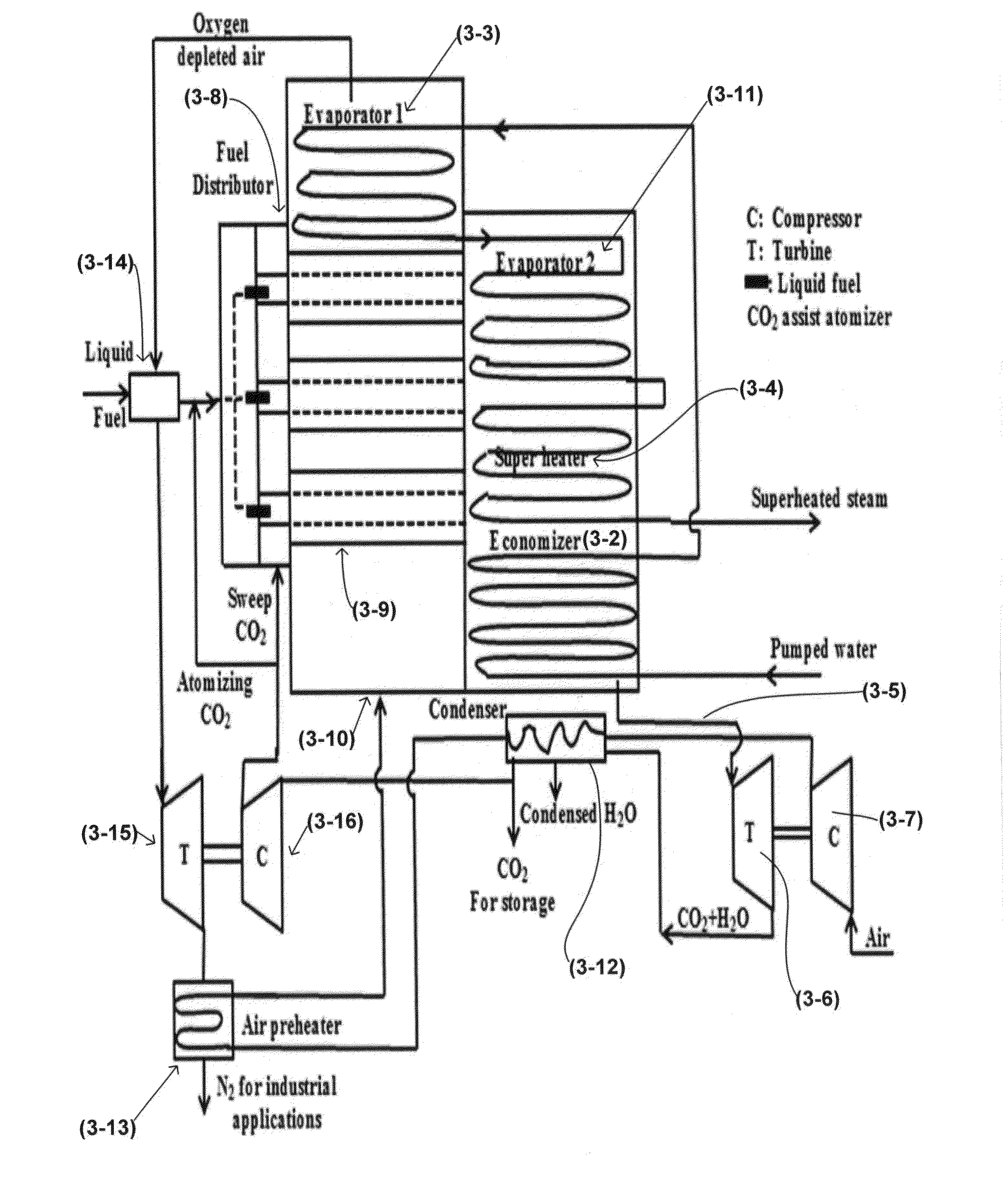
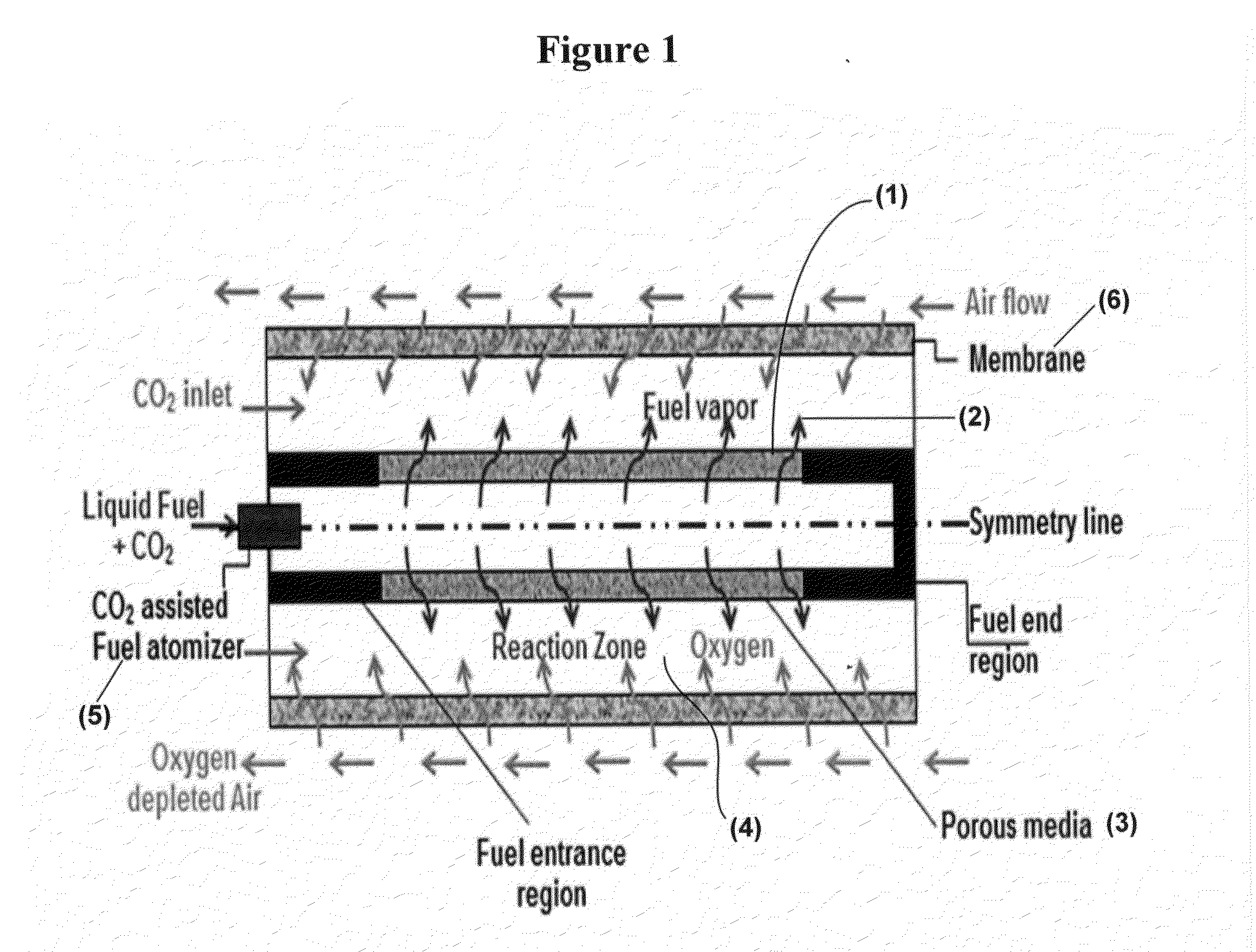
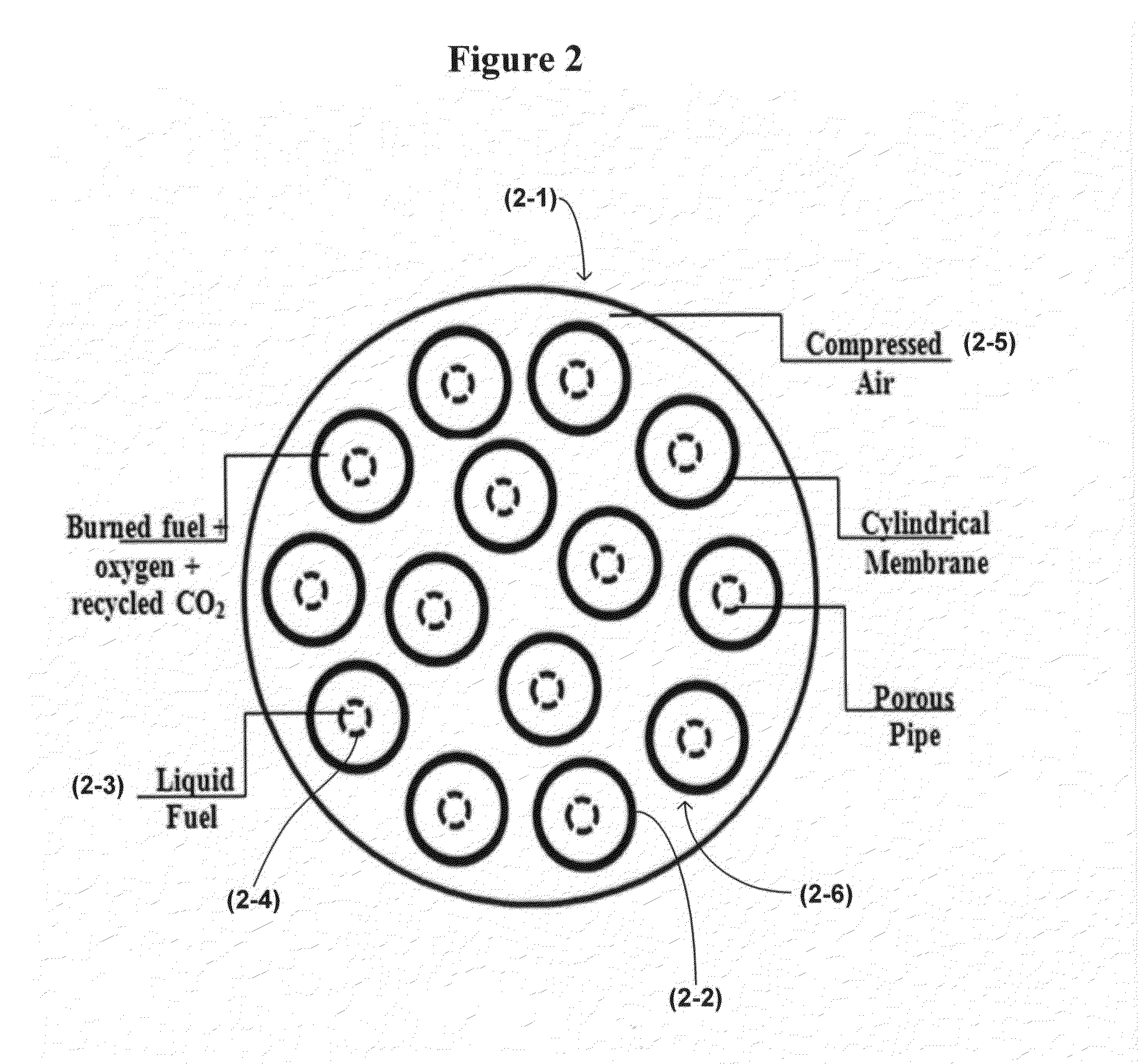
The present patent describes a new design for a liquid fuel oxygen transport reactor that includes an outer oxygen transport membrane, an inner porous membrane, a liquid fuel injector, and a gas-assisted fuel atomizer. The reactor can be used in a combustion chamber to generate mechanical energy for the generation of electricity or compression power. The technical effects of this design include improved fuel atomization, increased oxygen concentration, and improved combustion efficiency. Additionally, the patent describes the use of multiple oxygen transport reactors in a combustion chamber to improve power generation efficiency.

Problems solved by technology

Liquid fuels produce large amounts of carbon dioxide.
This process of separation of O2 is very costly (Sundkvist S, Griffin T, Thorshaug N. AZEP e development of an integrated air separation membrane e gas turbine.
The results show that although a reactive ITM significantly improves the partial pressure driving force, practical reactor engineering considerations indicate that this concept is not superior to counter-current separation-only ITMs, mainly because of the stringent temperature limitations of the membrane material; however, the temperature limit was acceptable in case of co-current flow.

Method used


Image

  • Carbon-free low-nox liquid fuel oxygen transport rector for industrial water tube boilers
  • Carbon-free low-nox liquid fuel oxygen transport rector for industrial water tube boilers
  • Carbon-free low-nox liquid fuel oxygen transport rector for industrial water tube boilers

Examples


Embodiment Construction

[0028]Referring now to the drawings, wherein like reference numerals designate identical or corresponding parts throughout the several views.

[0029]Conventional combustors of gas turbines and boiler furnaces are composed of fuel and air burners that are used to burn the liquid fuel producing exhaust gases composed mainly of carbon dioxide, nitrogen and water vapor. In order to separate the carbon dioxide of this mixture several energy-demanding chemical processes are required. In the present disclosure the conventional combustors and furnaces are replaced by furnaces and / or reactors that provide the ability of burning liquid fuel with oxygen to produce carbon dioxide and water vapor which can be easily separated through condensing the water vapor via simple cooling processes. Thus, carbon dioxide can be captured.

[0030]The present disclosure includes a carbon-free liquid fuel combustor which utilizes oxygen transport reactors for online and combined oxygen separation and combustion. W...


PUM


Abstract

An oxygen transport reactor for boiler furnaces and gas turbine combustors that utilizes a liquid fuel that is oxidized as a gaseous fuel in a membrane reactor. A liquid fuel is introduced by vaporizing the fuel inside a porous pipe surrounded by an annulus reaction zone which is surrounded by an annulus air zone. An oxygen transport membrane separates the annulus reaction zone containing the porous vaporized fuel and sweeping CO2 from the air feed side zone. Oxygen is transported from the outer annulus through the membrane to the annulus reaction zone containing the vaporized fuel and sweeping CO2. Fuel is first cracked to very small droplets in the intake fuel atomizer utilizing part of the intake CO2 then completely vaporized inside the porous pipe utilizing the heat coming from the surrounding reaction zone. The oxygen transport reactor is applicable for carbon free boiler furnaces and gas turbine combustors which utilize oxygen transport reactors for combined oxygen separation and combustion.

Description

BACKGROUND[0001]1. Field of the Disclosure[0002]The invention relates to a fuel oxygen transport reactor that may be used together with a turbine and / or a water tube boiler and a method of operating an oxygen transport reactor to obtain full evaporation of a liquid fuel prior to contact and combustion with an oxygen-enriched atmosphere.[0003]2. Description of the Related Art[0004]The “background” description provided herein is for the purpose of generally presenting the context of the disclosure. Work of the presently named inventors, to the extent it is described in this background section, as well as aspects of the description which may not otherwise qualify as prior art at the time of filing, are neither expressly or impliedly admitted as prior art against the present invention.[0005]Fossil fuels are considered to be a main source of energy for the developed and developing world. Fossil fuels produce CO2 which is thought to be a main contributor of global warming (Habib M. A., Ne...

Claims


Application Information

Patent Timeline
IPC IPC(8): F02C3/22F23C5/08F23L7/00
CPCF02C3/22F23C5/08F23L7/007F23D11/443Y02E20/34B01D63/06B01D69/04
Inventor HABIB, MOHAMED ABDEL-AZIZNEMITALLAH, MEDHAT AHMED
Owner KING FAHD UNIVERSITY OF PETROLEUM AND MINERALS
Learn More