Flow control system

a flow control and flow control technology, applied in the direction of liquid fuel feeders, machines/engines, transportation and packaging, etc., can solve the problems of reducing the control the correspondingly high cost reduction attention of the fuel injector, and the best of the prior art system, so as to reduce prevent the leakage rate of the system, and quick control the effect of respons

Active Publication Date: 2015-06-25
VOLVO LASTVAGNAR AB
View PDF6 Cites 5 Cited by
  • Summary
  • Abstract
  • Description
  • Claims
  • Application Information

AI Technical Summary

Benefits of technology

[0016]By extending the action of the mechanical resilient means of the control valve also to the shuttle valve, which is a part of the hydraulic amplification unit, a higher rate of leakage can be prevented. That extended action of the resilient means replaces the control flow that is otherwise necessary to initially re-pressurize the control chamber of the shuttle valve upon the flow control system's deactivation command, and thereby reduces the system's control leakage whilst achieving quick control response.
[0017]The slidable seat of the control valve may be precision-matched to its guide for limiting the leakage from the shuttle control chamber to the return port that bypasses the actual sealing surface of said seat and the control valve. The slidable seat may be further provided with an additional seating surface at its end stop that limits its movement away from the shuttle valve, such that when at the end stop, that seating surface would form a positive seal with the shuttle control chamber to completely prevent the seat bypass leakage. The shuttle valve may be provided with a differential area exposed to the pressure in the inlet port, in order to improve the force balance occurring on the valve and further shorten the response time to the command for terminating the controlled flow. Another enhancement of the flow control system may be embodied in the form of a poppet attached to the shuttle control valve between its seat and the main control chamber which may also be advantageously configured with a poppet restriction which replaces said fixed restriction between the main control chamber and the shuttle control chamber. By this means, the dynamic behaviour of the shuttle valve may be further improved for greater responsiveness, because the poppet restriction would help creating a positive pressure difference between the shuttle control chamber and the main control chamber and, at the same time, act to increase the effective area for the pressure in the shuttle control chamber and thereby facilitate a faster opening of the shuttle control valve to shorten the response time to the commands for terminating the controlled fluid flow.
[0019]Another embodiment of the present invention may also include a spill valve connected between the high pressure outlet and the volume with a relatively low pressure, for affording the inventive flow control system with an additional possibility of controlling the flow characteristics and providing extra safety features. According to this embodiment, the opening of the spill valve after the termination of the controlled fluid flow through the flow control system would relieve residual pressure between the main control valve and the nozzle and thus prevent possible undesired leakage through the nozzle that might lose its hydraulic tightness due to wear or other damage.
[0020]Yet another embodiment may be configured for further improved hydraulic efficiency, by having the spill valve installed between the return port and the volume with a relatively low pressure and the high-pressure outlet connected to the inlet of the spill valve. In this embodiment, the spill valve is closed before the control valve is open to begin the controlled fluid flow. This reduces the leakage out to the volume with a relatively low pressure, and instead directs the pressure relieved by the control valve in the beginning of the system opening into the inlet of the nozzle, so that less hydraulic energy from the outlet chamber of the main control valve would then be used to pressurize the nozzle inlet volume.BRIEF DESCRIPTION OF DRAWINGS

Problems solved by technology

At the same time, being a significant contributor to the overall cost of the engine, the fuel injector is receiving correspondingly high cost reduction attention.
However, even the best of the prior art systems have certain drawbacks.
For example, the flow control systems that utilize a 3-way solenoid actuator, while benefiting from the advantages this may give in terms of control precision, have a relatively high cost and complexity associated with that actuator, making this approach feasible only for a very few select manufacturers but also carrying their own particular durability and efficiency concerns.
In addition, this kind of prior art flow control systems / injectors require a compromise to be made between the hydraulic efficiency (the rate of control leakage) and the response time, especially that associated with the closure of the valve / end of injection.
As mentioned above in the discussion of the prior art, in flow control systems based on the use of a simple two-way control valve coupled to a hydraulic amplification stage to handle the throughput of the high hydraulic power, there is a conflict between the controllability of the flow control system and its hydraulic efficiency.
That higher rate of control flow usually entails also a higher rate of control leakage and, as a consequence, worse hydraulic efficiency of the entire system and other undesirable effects such as for example excessive fluid heat-up.

Method used


Image

  • Flow control system
  • Flow control system
  • Flow control system

Examples


Embodiment Construction

[0028]Various aspects of the invention will hereinafter be described in conjunction with the appended drawings provided to illustrate and not to limit the invention, wherein like designations denote like elements.

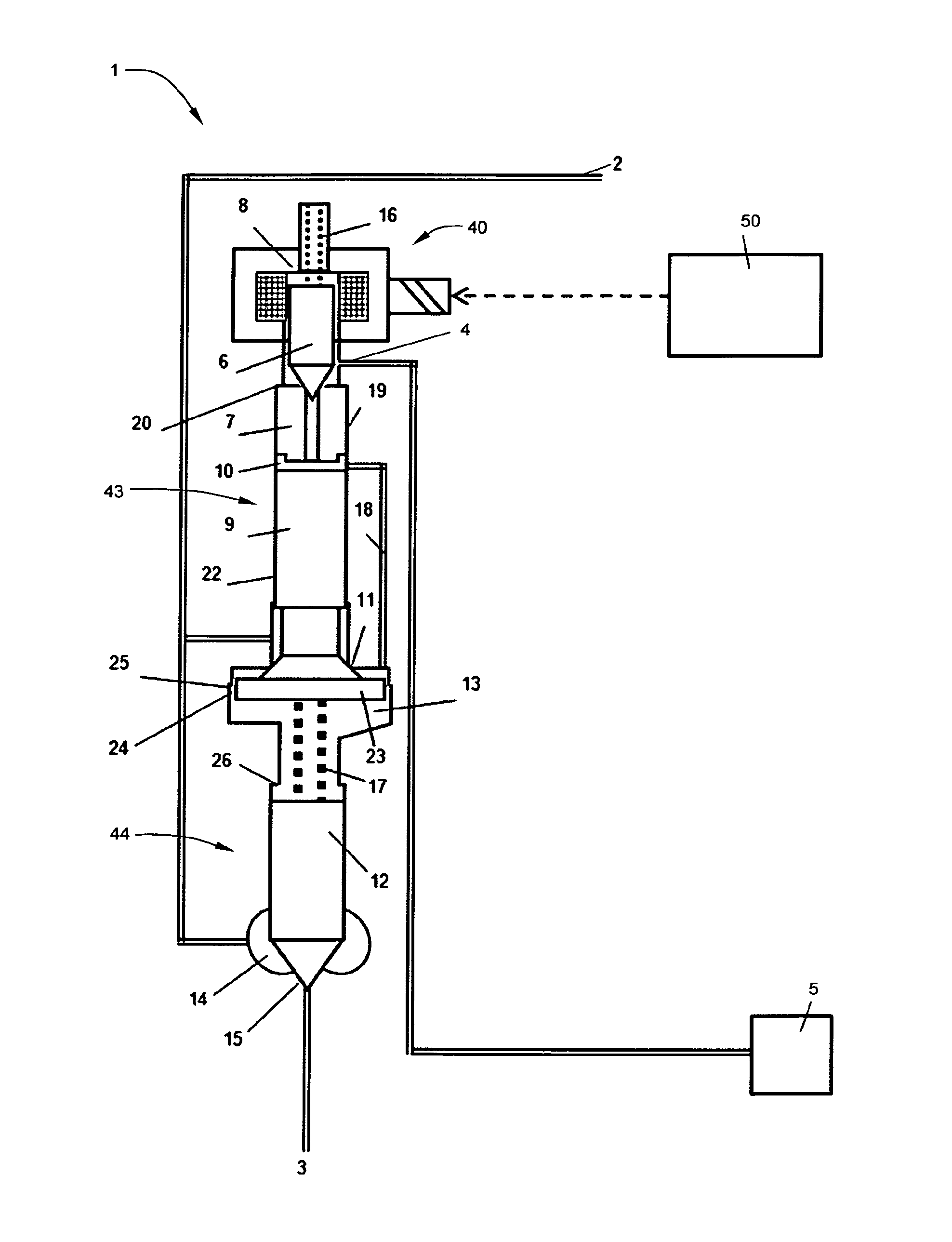
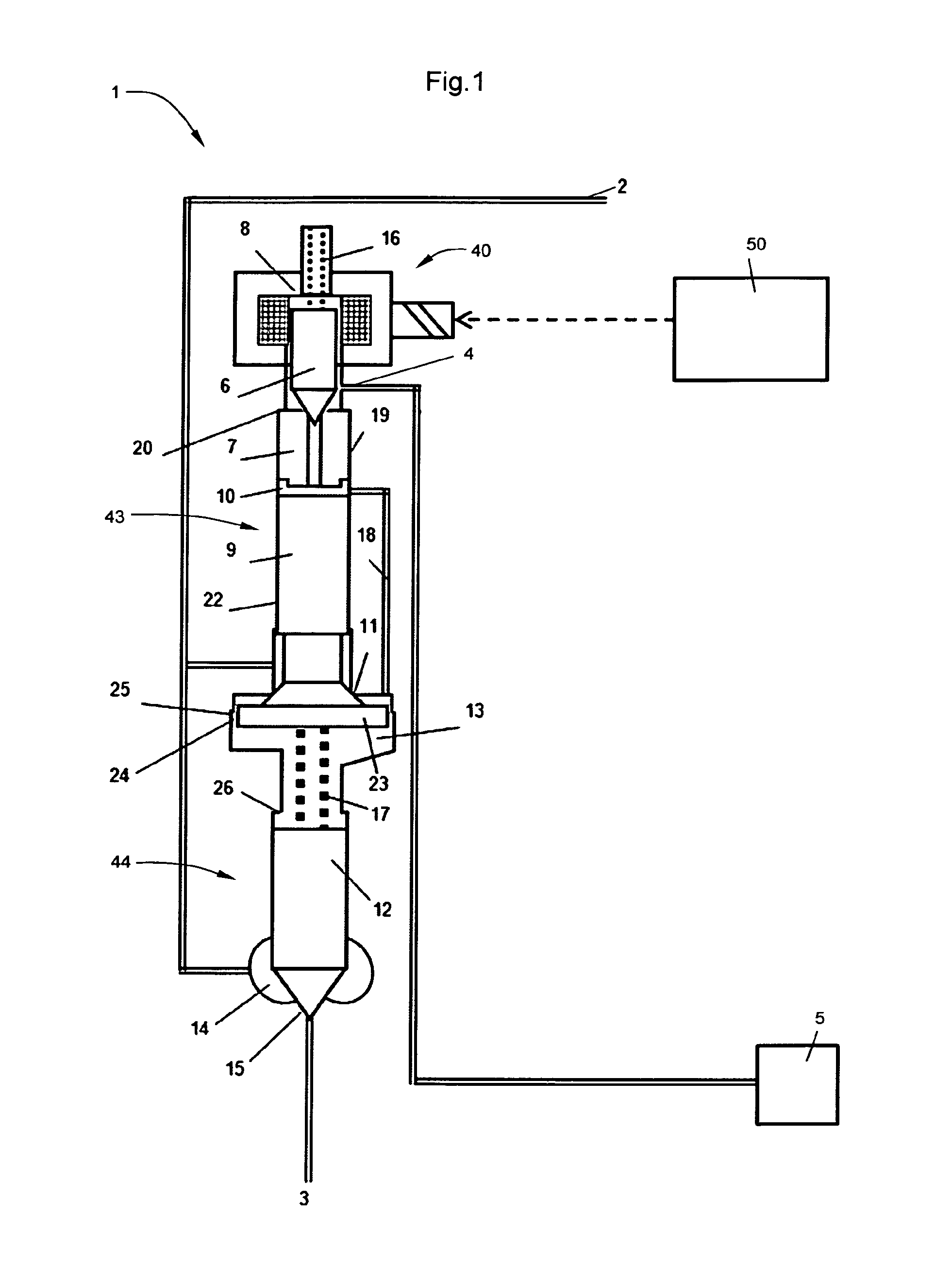
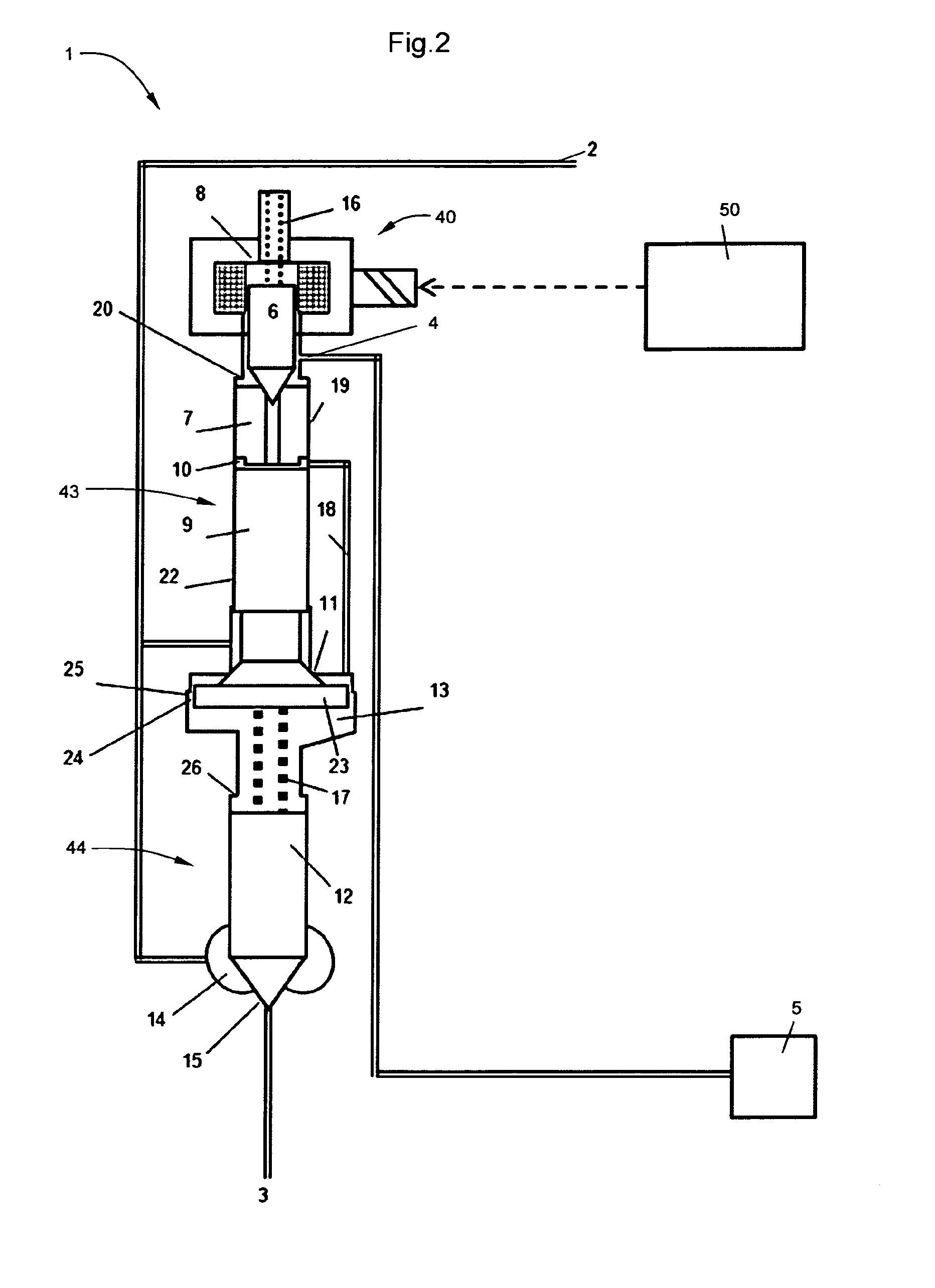
[0029]FIG. 1 schematically shows a first embodiment of the flow control system 1 according to the invention. The system 1 comprises an inlet 2 for pressurized fluid, an outlet 3 for pressurized fluid, a return port 4 connected to a volume 5 having a relatively low pressure, a control valve 40 with a control valve member 6, a first seat 7 and a first abutment 8 that limits the lift of said control valve member 6 away from said first seat 7, a shuttle valve 43 with a shuttle valve body 9, 47, shuttle control chamber 10 and a third seat 11, and a main valve 44 with a main control chamber 13, an outlet chamber 14 and a second seat 15, wherein said control valve 40 is connected between the shuttle control chamber 10 and the return port 4 and is biased towards its closed position...


PUM


Abstract

A flow control system for a fuel injector for an internal combustion engine is provided and includes an inlet port, an outlet, a return port, a 2-way control valve including a control valve member, a shuttle valve and a main valve. The control valve includes a first seat, a first resilient arrangement configured to force the control valve member towards the seat so as to close the control valve, and a first abutment that limits the lift of the control valve member away from the first seat. The first seat of the control valve is slidably arranged in the shuttle control chamber. An end stop for the first seat is provided such that the pressure in a shuttle control chamber tends to move the first seat towards the end stop. The first seat, upon its mechanical contact with a valve member is able to transmit at least a part of the force of the resilient means onto a shuttle valve body in the opening direction of the shuttle valve.

Description

BACKGROUND AND SUMMARY[0001]This invention relates to a flow control system, in particular for a fuel injector for an internal combustion engine.[0002]In fluid power applications, flow control systems are important constituents that directly define accuracy, reliability, efficiency and cost of the device / installation they belong to. Correspondingly, a flow control system must consume a minimum of energy to control the given fluid power, while being inexpensive, simple, reliable and durable and fulfilling the necessary control accuracy demands. One example of an especially demanding application for a flow control system is a diesel fuel injector. Contemporary diesel fuel injection systems of, for instance, a heavy-duty truck engine are required to deliver high hydraulic power in extraordinarily short bursts with an almost unthinkable accuracy: an instantaneous fluid power in the order of 40 kW can be routinely achieved, its delivery precisely controlled and then fully terminated, all...

Claims


Application Information

Patent Timeline
Patent Type & Authority Applications(United States)
IPC IPC(8): F02M63/00
CPCF02M63/0049F02M63/0029F02M63/0033F02M37/0029F02M63/0043F02M37/0023F02M47/02F02M63/0045F02M47/027F02M55/002Y10T137/87193F02M63/0005F02M63/0007
Inventor YUDANOV, SERGI
Owner VOLVO LASTVAGNAR AB
Why Eureka
Try Eureka