Cam follower roller device

a follower roller and roller technology, applied in the direction of mechanical equipment, machines/engines, fuel injecting pumps, etc., can solve the problems of limited frictional torque of the device, limited roller and body, and wear generated by axial contact between the friction element or elements, etc., to achieve easy manufacture and assembly, and reduce frictional torque

Active Publication Date: 2015-06-25
AB SKF
View PDF6 Cites 10 Cited by
  • Summary
  • Abstract
  • Description
  • Claims
  • Application Information

AI Technical Summary

Benefits of technology

[0008]The present invention aims to provide a cam follower roller device having reduced frictional torque and which is easy to manufacture and to assemble.
[0010]The interposition of at least one friction element axially between the roller and the body makes it possible to avoid direct axial contact between these two components. The frictional torque of the device is thus limited. The wear generated by axial contact between the friction element or elements, the roller and the body is limited.
[0013]Advantageously, the friction element or elements are mounted freely on the shaft. The friction element or elements may be mounted freely in rotation on the shaft.
[0014]The floating or free assembly of the friction element or elements on the shaft makes it possible to further reduce the frictional torque of the device. Specifically, during operation, the friction element or elements may be driven to rotate by the roller but at a speed lower than that of the latter. Thus, the friction between the roller and the friction element or elements is small.

Problems solved by technology

The frictional torque of the device is thus limited.
The wear generated by axial contact between the friction element or elements, the roller and the body is limited.

Method used


Image

  • Cam follower roller device
  • Cam follower roller device
  • Cam follower roller device

Examples


Embodiment Construction

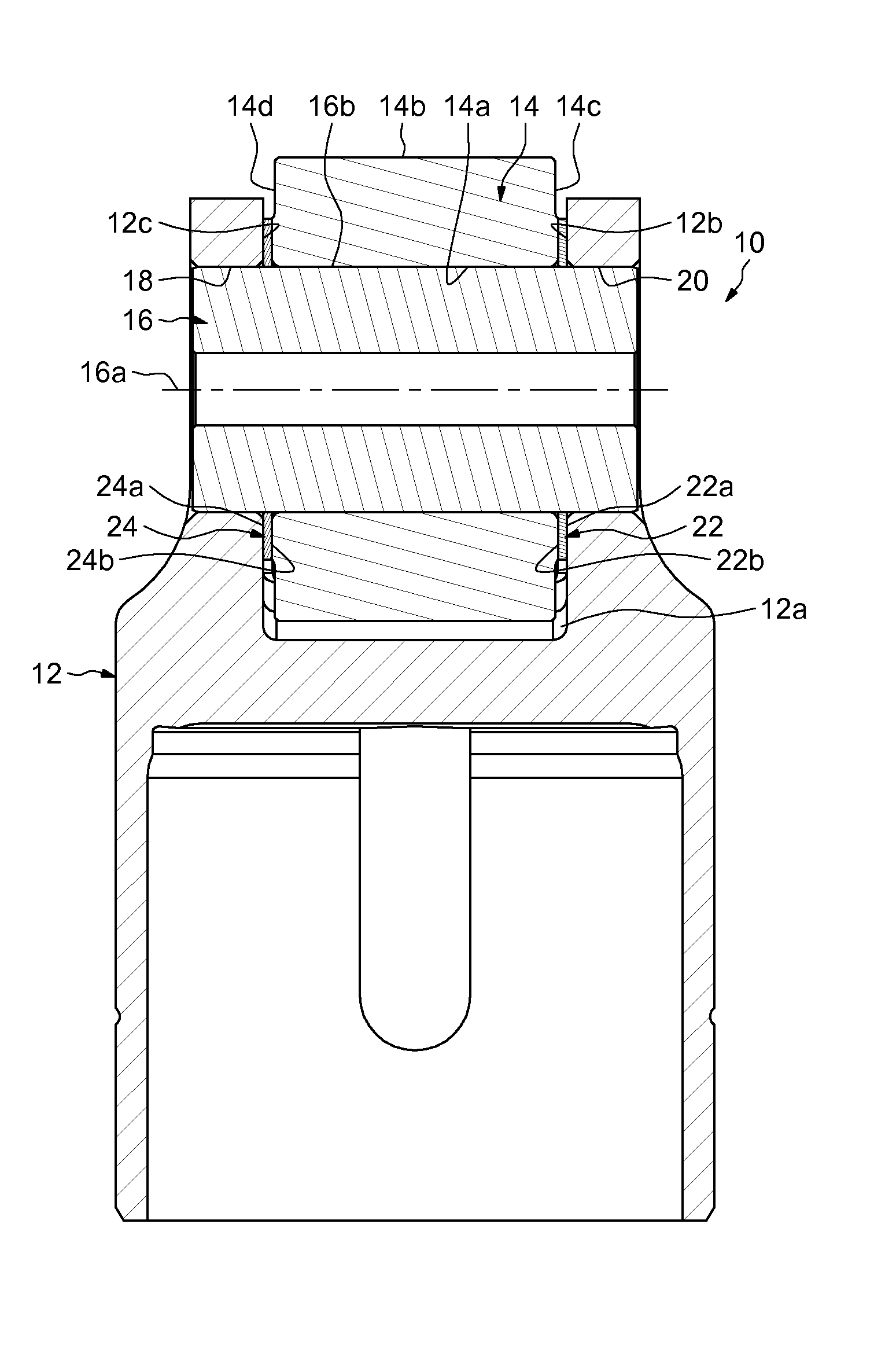
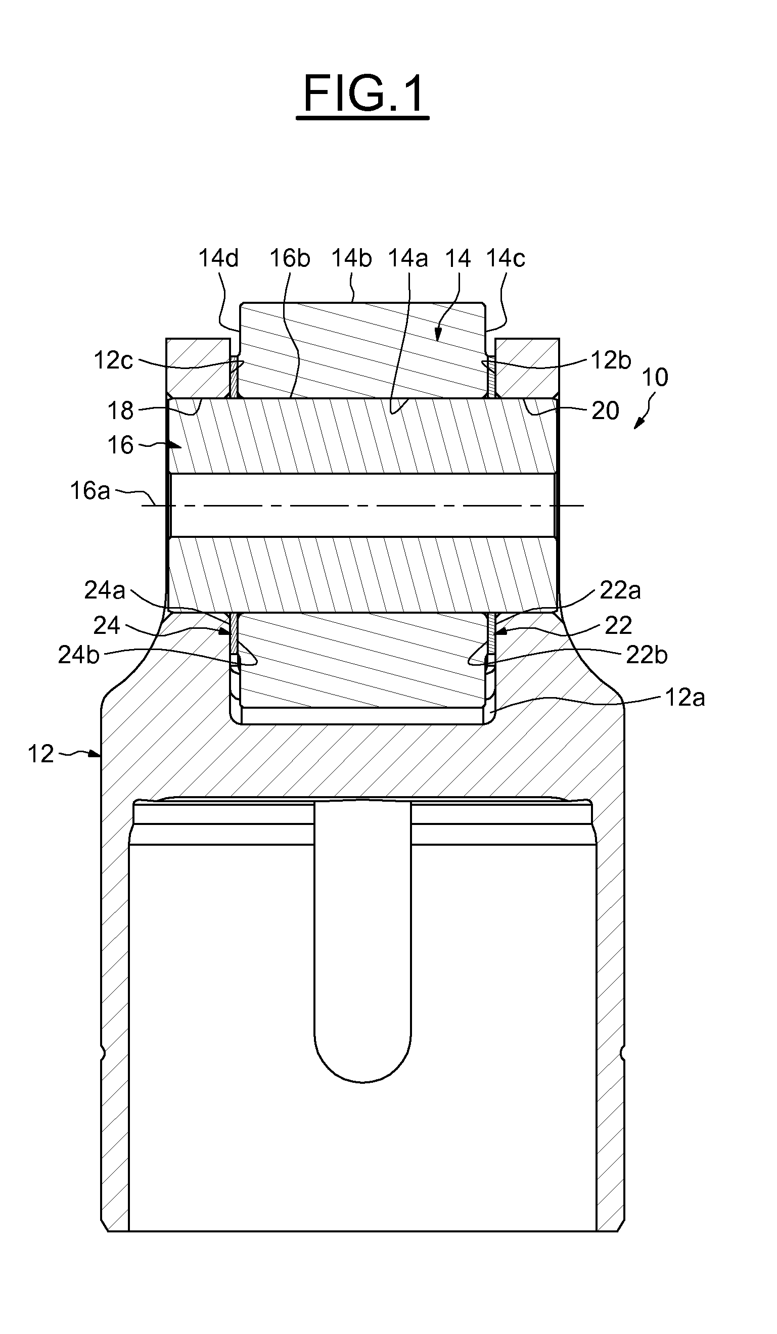
[0024]FIG. 1 shows a cam follower roller device, designated by the general reference number 10, which can for example be used in a fuel injection pump intended for an internal combustion engine.

[0025]The device 10 comprises a tappet or body 12 and a roller 14 mounted to rotate with respect to the body and intended to bear against a cam synchronized with the camshaft of the internal combustion engine or directly against a cam of the shaft. The body 12 delimits an outwardly open recess 12a inside which the roller 14 is mounted. The body 12 comprises two opposed radial front inner walls 12b, 12c axially delimiting the recess 12a. The roller 14 extends so as to project radially outside the body 12. The body 12 may advantageously be obtained at low cost by forging or by cutting, stamping and bending from a blank of thin metal sheet.

[0026]The device 10 also comprises a shaft 16, of geometric axis 16a, mounted on the body 12 and supporting the roller 14. The support shaft 16 comprises an a...


PUM


Abstract

The cam follower roller device including a body, a shaft mounted on the body, a roller mounted on the shaft in a rotationally movable manner, and at least one friction element mounted on the shaft axially between the roller and the body. The friction element is separate from the body and from the roller.

Description

CROSS REFERENCE TO RELATED APPLICATION[0001]This is a United States Non-Provisional Patent Application claiming the benefit of France Patent Application Number FR1363389 filed on 23 Dec. 2013, which is incorporated herein by reference in its entirety.TECHNICAL FIELD OF THE INVENTION[0002]The present invention relates to the field of cam follower roller devices used in automotive or industrial applications.BACKGROUND OF THE INVENTION[0003]One advantageous application of the invention is the use of the cam follower roller device in a fuel injection pump intended for an internal combustion engine, in particular of a motor vehicle such as an automobile or lorry.[0004]A device such as this comprises a tappet or body and a roller mounted to rotate on the body and intended to cooperate with a cam synchronized with the camshaft of the internal combustion engine so that the rotation of the camshaft leads to a periodic displacement of a piston of the injection pump that bears against the body...

Claims


Application Information

Patent Timeline
Patent Type & Authority Applications(United States)
IPC IPC(8): F16H53/06F16C13/02
CPCF16C13/02F16H53/06F02M59/102F02M59/44F02M59/445F02M2200/9038F02M2200/02F01L1/14Y10T74/2107F01L2305/02F01L2305/00
Inventor CHAMPALOU, FRANCOISCORBETT, RICHARDGHILBERT-SIMON, AURELIENHAUVESPRE, BENO TMAFFUCCI, JULIEN
Owner AB SKF
Why Eureka
Try Eureka