Uninterruptible power supply apparatus

Inactive Publication Date: 2015-06-25
FUJI ELECTRIC CO LTD
View PDF9 Cites 32 Cited by
  • Summary
  • Abstract
  • Description
  • Claims
  • Application Information

AI Technical Summary

Benefits of technology

[0028]According to the uninterruptible power supply apparatus with such a configuration, the first battery unit provided in parallel with the power supply unit can be used as a measure to deal with a power outage, and the second battery unit can be used as an auxiliary unit for supplementing the power supply capability of the power supply unit in accordance with the amount of power required by the loading device and the availability of the AC power. Therefore, while the original functions of the uninterruptible power supply apparatus are established by the first battery unit, the operation of the second battery unit can be controlled, resulting in a reduction of the burden on the power supply unit and hence its power consumption.
[0029]More specifically, the controller operates the power supply unit and the first and second battery units in a correlated manner in accordance with the amount of power required by the loading device. Therefore, the peak power consumption of the power supply unit can be cut when, for example, the problem in supply of power becomes severe in the system power supply. Furthermore, when the power consumption of the power supply unit increases as a result of an increase in the power consumption of the loading device, the sec

Problems solved by technology

Naturally, a large space to install the uninterruptible power supply apparatus 1 is needed.
Furthermore, use of a plurality of the uninterruptible power supply apparatuses 1 in parallel as described in Patent Documents 2 and 3, leads to a complicated system configuration.
In addition, the uninterruptible power supply apparatus 1 can only

Method used


Image

  • Uninterruptible power supply apparatus
  • Uninterruptible power supply apparatus
  • Uninterruptible power supply apparatus

Examples


Embodiment Construction

[0037]An uninterruptible power supply apparatus according to an embodiment of the present invention is described hereinafter with reference to the drawings.

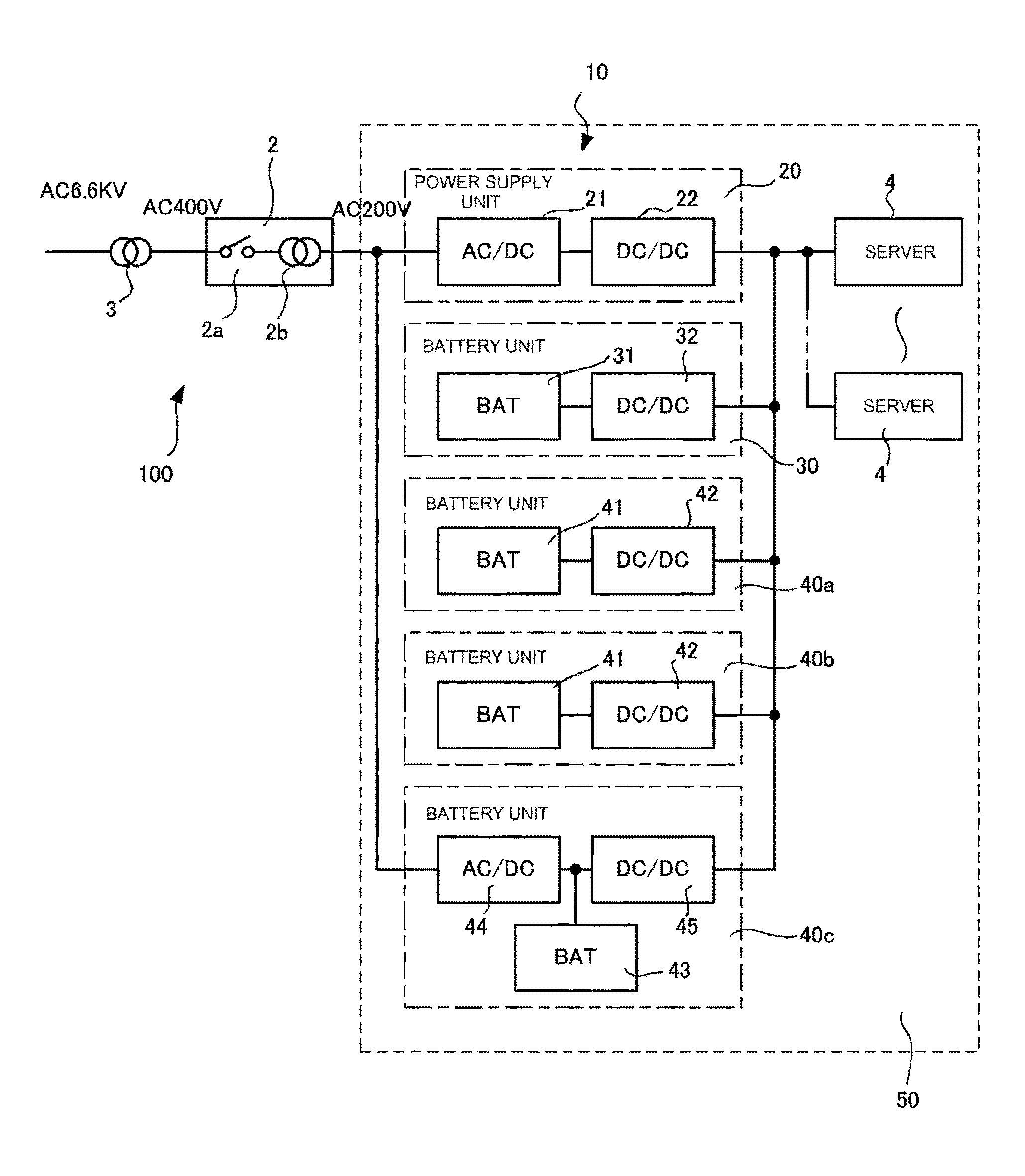
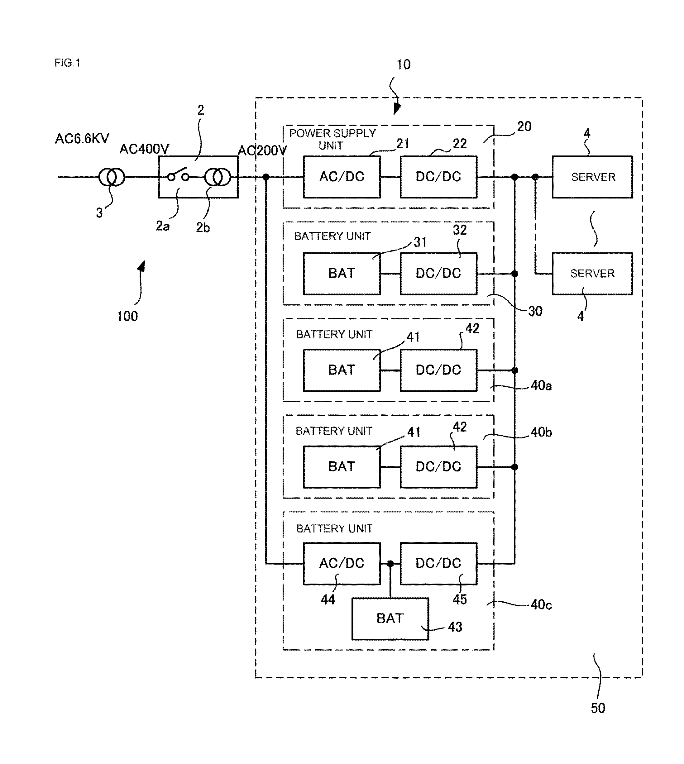
[0038]FIG. 1 is a schematic configuration diagram of a power supply system 100 constructed with an uninterruptible power supply apparatus 10 according to an embodiment. This power supply system 100 is a favorable system for supplying a DC voltage of 12 V to each of a plurality of servers (loading devices) 4 constructing a multimode server in, for example, a data center, to drive the servers 4. Note in FIG. 1 that the components same as those of a conventional power supply system are given same reference numerals.

[0039]This power supply system 100 has an AC power distributor (PDU) 2 connected to a 400 V system power supply and supplies AC power to a server rack 50 through this power distributor 2, the server rack 50 having the plurality of servers (loading devices) 4 stored therein. In the power supply system 100 shown in FIG. 1, ...


PUM


Abstract

An uninterruptible power supply apparatus includes a power supply unit converting AC power to generate a DC voltage to be supplied to a loading device. The uninterruptible power supply apparatus further includes a first battery unit connected to the power supply unit to receive a DC current therefrom, and stores first DC power generated from the DC voltage. The first battery unit generates a DC voltage to be supplied to the loading device from the first DC power. The uninterruptible power supply apparatus includes a second battery unit connected in parallel to the power supply unit and stores second DC power, and generates, from the second DC power stored in the second battery unit, a DC voltage to be supplied to the loading device. The uninterruptible power supply apparatus further includes a controller for controlling operation of the power supply unit, the first battery unit and the second battery unit.

Description

[0001]This application is a continuation under 35 U.S.C. 120 of International Application PCT / JP2013 / 057566 having the International Filing Date of Mar. 15, 2013, which is fully incorporated herein by reference.TECHNICAL FIELD[0002]The present invention relates to an uninterruptible power supply apparatus capable of conserving electric energy by efficiently supplying power to a loading device in accordance with the amount of power required by the loading device and the availability of AC power.BACKGROUND ART[0003]FIG. 6 is a schematic configuration diagram of a general, conventional power supply system of a data center with a plurality of loading devices such as a plurality of servers that use DC voltage as the driving power supply. This power supply system has an uninterruptible power supply apparatus (UPS) 1 interposed in a 400 V system power supply, and an AC power distributor (PDU) 2 for converting high-voltage AC power (AC 400 V), supplied through the uninterruptible power supp...

Claims


Application Information

Patent Timeline
IPC IPC(8): H02J1/08H02J7/34
CPCH02J7/34H02J1/08G06F1/263H02J1/102H02J7/35H02J9/062H02J2300/28Y02B10/70G06F1/00Y02E10/76
Inventor YAMADA, RYUJIMINO, KAZUAKISHIMIZU, RYUJIKADOI, HIROKAZUKAWAGUCHI, KOJI
Owner FUJI ELECTRIC CO LTD
Why Eureka
Try Eureka