Molecular pump

a technology of molecular pump and pump body, which is applied in the direction of non-positive displacement pumps, motors, liquid fuel engines, etc., can solve problems such as failure or malfunction, and achieve the effects of preventing condensation formation, ensuring stability, and ensuring accuracy

Active Publication Date: 2015-07-02
OSAKA VACUUM
View PDF2 Cites 20 Cited by
  • Summary
  • Abstract
  • Description
  • Claims
  • Application Information

AI Technical Summary

Benefits of technology

[0027]According to the present invention, there is provided a molecular pump that can continuously, stably, and accurately calculate a relative humidity in the portion wh...

Problems solved by technology

If such condensation forms, attachment of a condensation liquid to ...

Method used


Image

  • Molecular pump
  • Molecular pump
  • Molecular pump

Examples


first embodiment

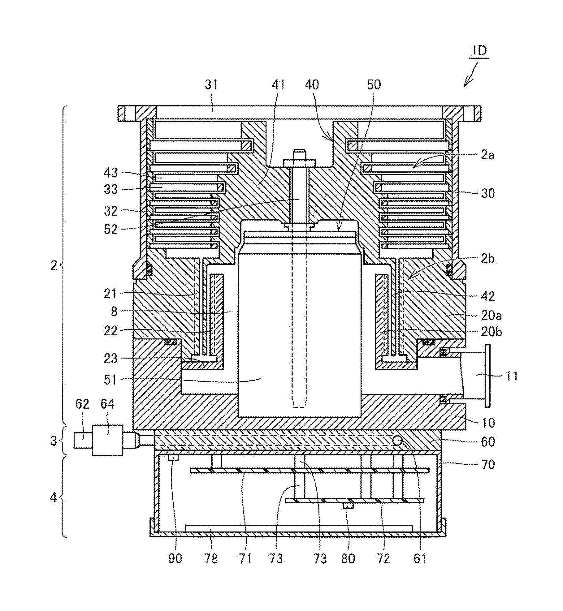
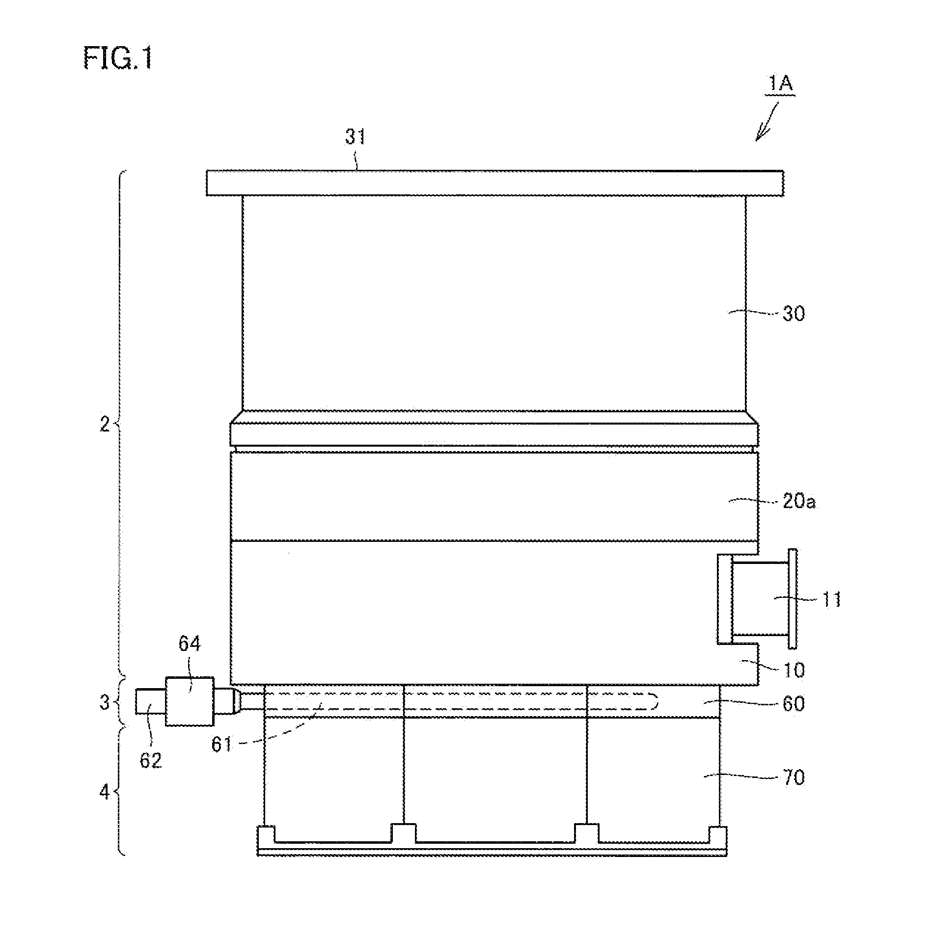
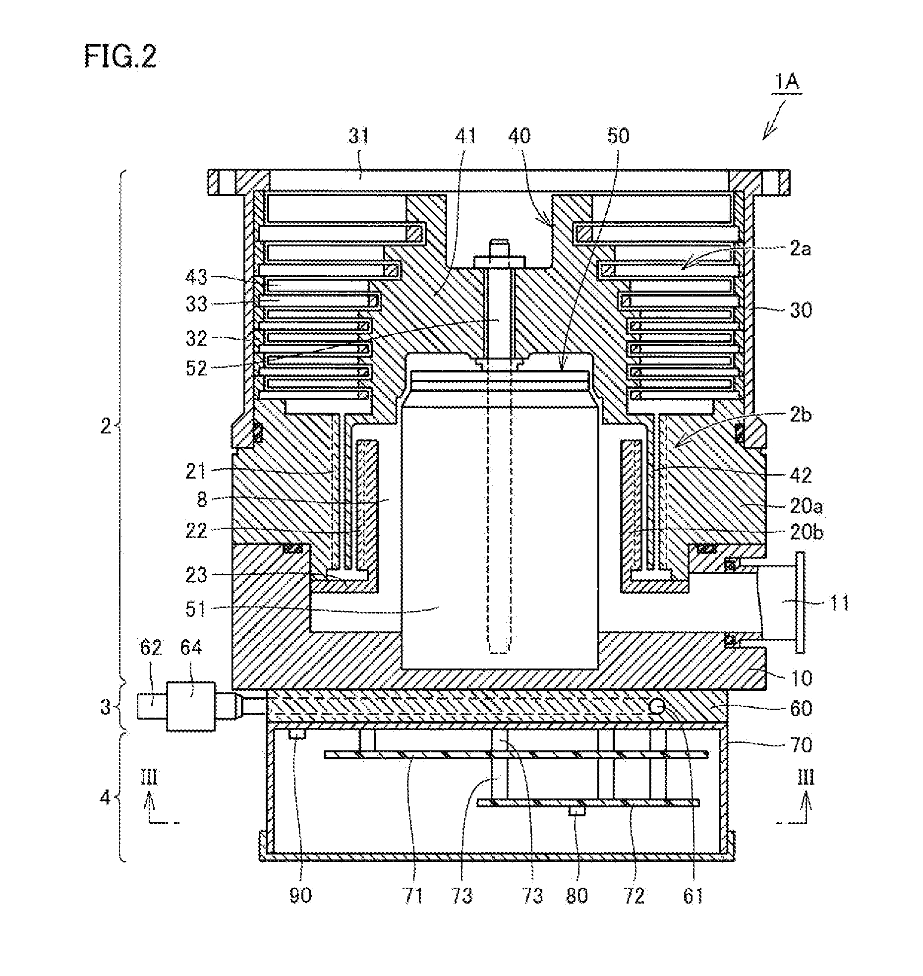
[0045]FIG. 1 is a front view of a molecular pump according to a first embodiment of the present invention. FIG. 2 is a schematic vertical cross-sectional view of the molecular pump shown in FIG. 1, and FIG. 3 is a schematic horizontal cross-sectional view of the molecular pump along line III-III shown in FIG. 2. FIG. 4 is a diagram illustrating a functional block of the molecular pump shown in FIG. 1. Referring to FIGS. 1 to 4, the configuration of a molecular pump 1A according to this embodiment will be described first.

[0046]As shown in FIGS. 1 and 2, molecular pump 1A according to this embodiment includes a pump body 2, a single cooling unit 3, and a control unit 4. Pump body 2, cooling unit 3, and control unit 4 are vertically stacked on one another. More specifically, cooling unit 3 is disposed on control unit 4, and pump body 2 is disposed on cooling unit 3. Cooling unit 3 is thus sandwiched between pump body 2 and control unit 4.

[0047]Pump body 2 is for creating an ultra-high ...

second embodiment

[0144]FIG. 13 is a partial cutaway front view of the molecular pump according to a second embodiment of the present invention, and FIG. 14 is a bottom view of the molecular pump shown in FIG. 13. Referring to FIGS. 13 and 14, a molecular pump 1E according to this embodiment will be described hereinafter.

[0145]As shown in FIGS. 13 and 14, molecular pump 1E according to this embodiment differs from molecular pump 1A according to the foregoing first embodiment only in the layout of pump body 2, single cooling unit 3, and control unit 4. Specifically, in molecular pump 1E, pump body 2 and control unit 4 are horizontally disposed adjacent to each other, and both are disposed on cooling unit 3. Consequently, pump body 2 and control unit 4 are arranged side-by-side on cooling unit 3.

[0146]As is clear from this configuration, in molecular pump 1E according to this embodiment also, cooling unit 3 and pump body 2 are arranged in contact with each other to be brought into thermal contact, and ...

third embodiment

[0149]FIG. 15 is a partial cutaway front view of a molecular pump according to a third embodiment of the present invention, and FIG. 16 is a bottom view of the molecular pump shown in FIG. 15. Referring to FIGS. 15 and 16, a molecular pump 1F according to this embodiment will be described hereinafter.

[0150]As shown in FIGS. 15 and 16, molecular pump 1F according to this embodiment differs from molecular pump 1E according to the foregoing second embodiment only in that a pair of cooling units 3 are provided, with one cooling unit 3 for pump body 2 and the other for control unit 4. Specifically, in molecular pump 1F, pump body 2 is arranged on cooling block 60A of one cooling unit 3, and control unit 4 is arranged on cooling block 60B of the other cooling unit 3.

[0151]Each of the pair of cooling units 3 has cooling liquid passage 61 provided in each of cooling blocks 60A and 60B, as well as inlet port 62, outlet port 63, and opening / closing valve 64 as a piping system connected to coo...


PUM


Abstract

A molecular pump includes a pump body provided with a turbo molecular pump portion, a control unit provided with a control portion and a power supply portion, and a cooling unit for cooling the pump body and the control unit. A first temperature detecting portion is provided in a first position, which is a position inside the control unit and has a low temperature. A second temperature detecting portion also serving as a humidity detecting portion is provided in a second position, which is a position inside the control unit and has a high temperature. The control portion controls the operation of the cooling unit in accordance with a relative humidity in the first position, calculated based on temperature information detected by the first temperature detecting portion and based on temperature information and humidity information detected by the second temperature detecting portion also serving as a humidity detecting portion.

Description

TECHNICAL FIELD[0001]The present invention relates to a molecular pump, which is a type of vacuum pump for creating an ultra-high vacuum, and more particularly to a molecular pump including a cooling unit as a cooling system.BACKGROUND ART[0002]Molecular pumps are attached as vacuum pumps for creating an ultra-high vacuum to various processing apparatuses represented by, for example, semiconductor manufacturing apparatuses, various analytical apparatuses, electron microscopes, and the like. A molecular pump generally includes a pump body provided with a turbo molecular pump portion including rotor blades and stator blades, and a control unit that accommodates a control portion for controlling the operation of the turbo molecular pump portion and a power supply portion for supplying electric power for driving the turbo molecular pump portion.[0003]In the molecular pump, the power supply portion included in the control unit includes a booster circuit, a converter circuit, an inverter ...

Claims


Application Information

Patent Timeline
IPC IPC(8): F04D19/04F04D27/00F04D29/58
CPCF04D19/042F04D27/00F04D29/58F04D29/5813F04D29/584F04D25/068F04D29/706
Inventor YAMATO, YUKIOOBAYASHI, TETSURO
Owner OSAKA VACUUM
Why Eureka
Try Eureka