
Antenna device and electrical device including the same

an antenna device and electrical device technology, applied in the direction of resonant antennas, substantially flat resonant elements, transmission, etc., can solve the problems of limited inducing resonance at a target frequency, degrading radiation performance, and limited inducing resonance at some frequency bands

Active Publication Date: 2015-07-02
SAMSUNG ELECTRONICS CO LTD
View PDF30 Cites 11 Cited by
  • Summary
  • Abstract
  • Description
  • Claims
  • Application Information

AI Technical Summary

Benefits of technology

The patent text explains that communication technologies like CDMA, GSM, and WCDMA use different frequency bands for wireless communication. However, with the rise of LTE and other advanced technologies, different nations or regions may use different frequency bands for communication. The patent aims to address this issue by providing antenna structures that allow for roaming and platformization of antennas between countries that use different communication frequency bands. This would mean that the antennas can be used across different nations without needing to change them.

Problems solved by technology

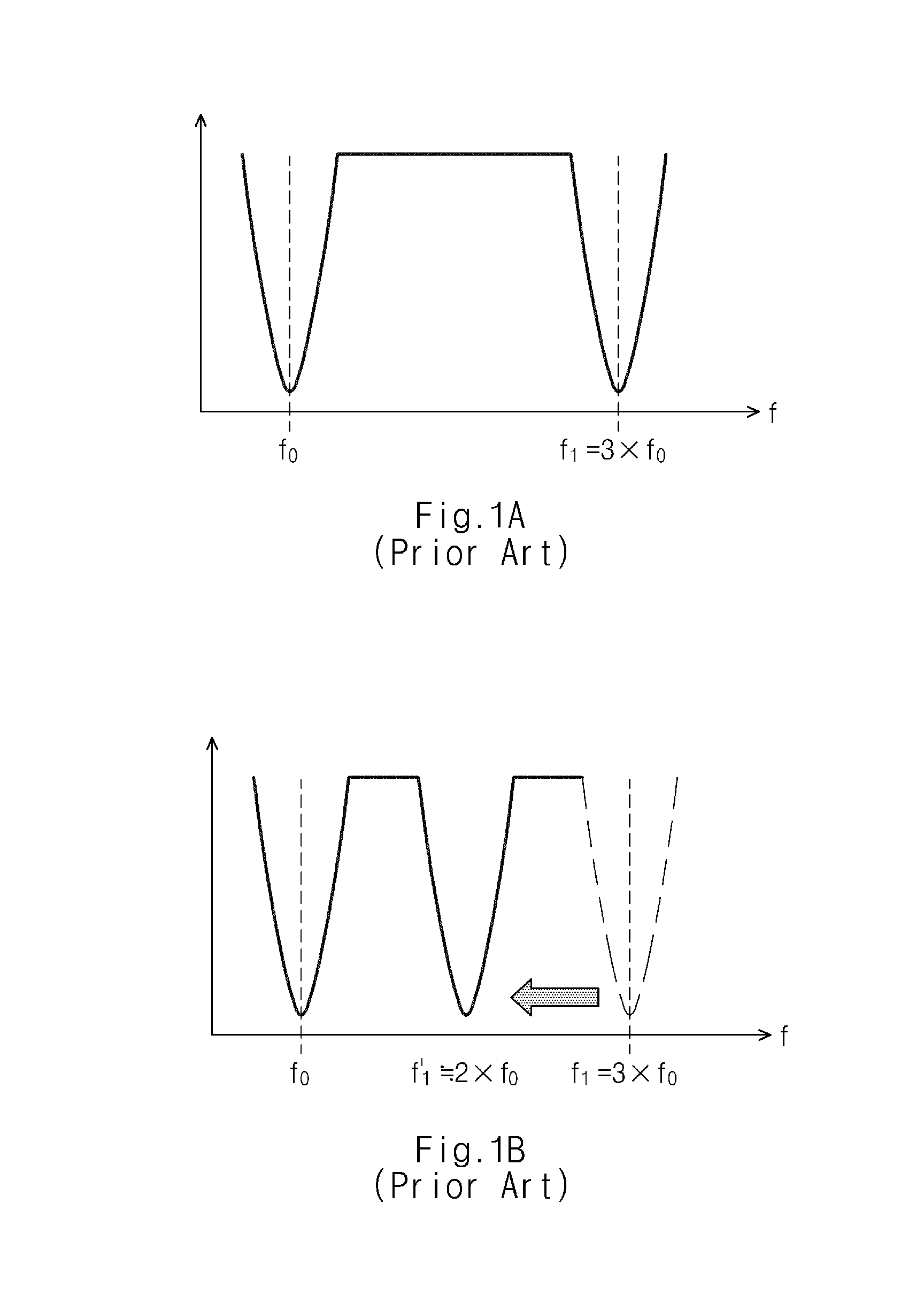
However, inducing resonance is limited at some frequency bands due to limitation in space for implementing an antenna (e.g. branch) pattern.
However, inducing resonance at a target frequency is limited due to various conditions.
Furthermore, if an additional pattern is added, radiation performance may be degraded due to an insufficient space for mounding an antenna.

Method used


Image

  • Antenna device and electrical device including the same
  • Antenna device and electrical device including the same
  • Antenna device and electrical device including the same

Examples


Embodiment Construction

[0035]Hereinafter, embodiments of the present invention are described in detail with reference to the accompanying drawings.

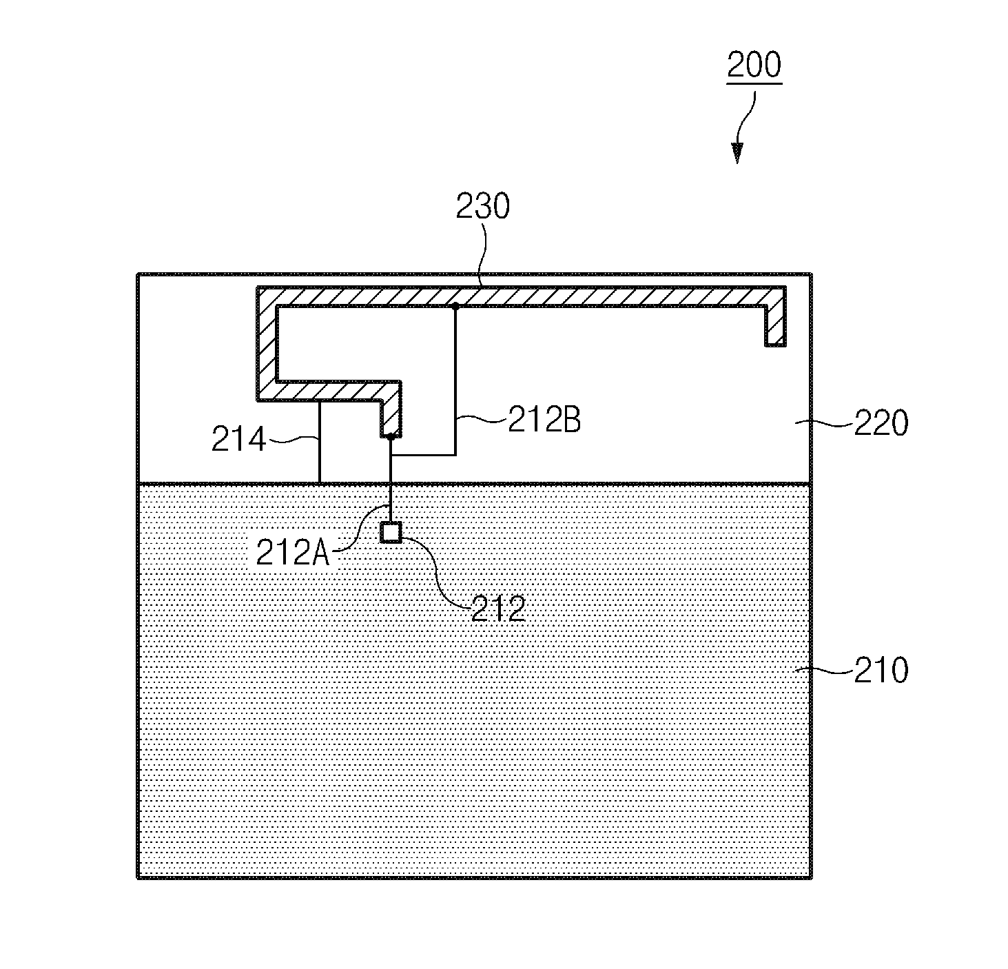
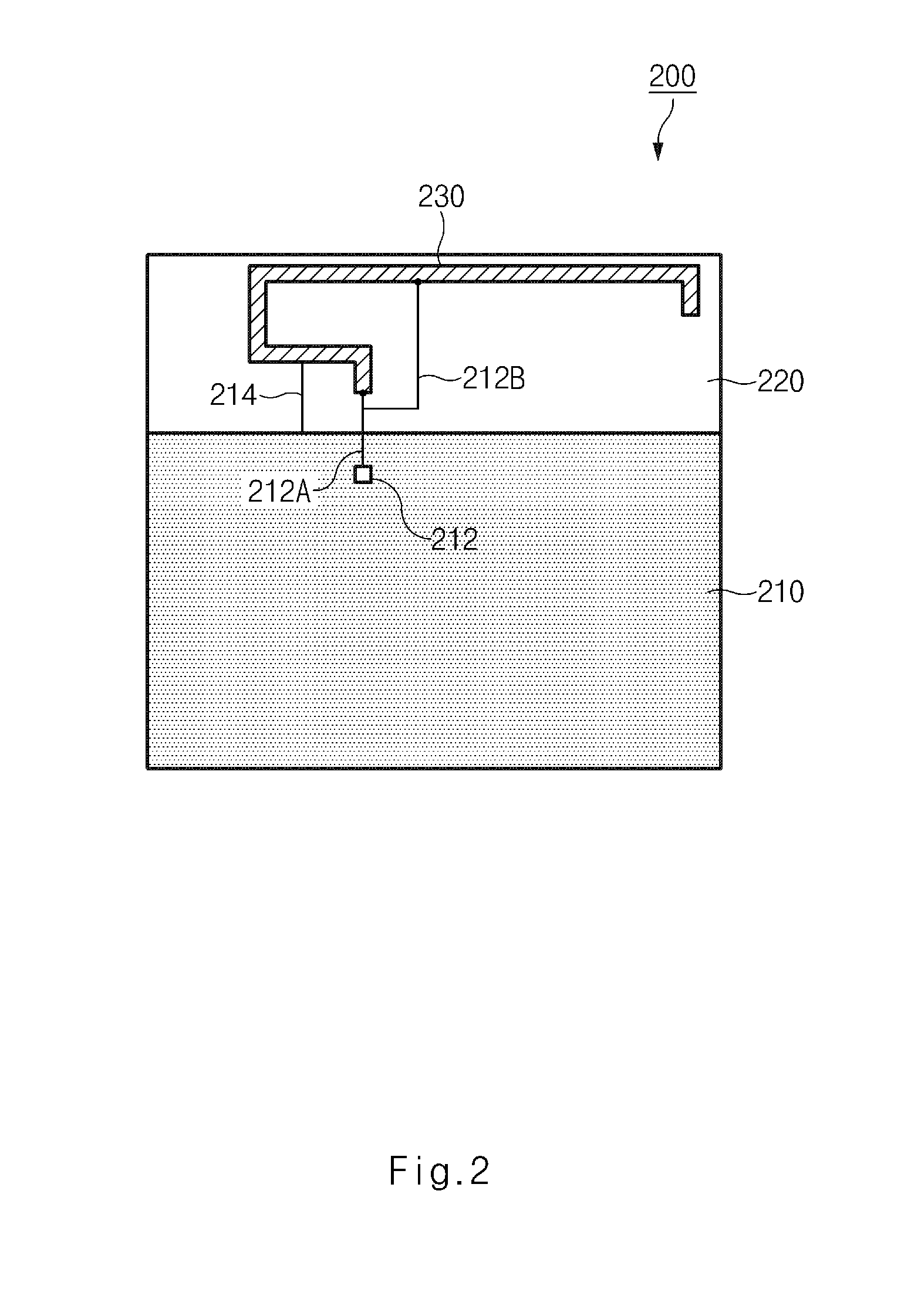
[0036]FIG. 2 is a diagram illustrating a PCB embedded antenna device built into an electronic device according to an embodiment of the present invention.

[0037]Referring to FIG. 2, an antenna device 200 includes a ground portion 210, a non-ground portion 220 and an antenna pattern 230. The antenna pattern 230 is connected to a feeding portion 212 and is connected to the ground portion 210 via a ground line 214. The antenna pattern 230 illustrated in FIG. 2 forms the shape of a PCB embedded antenna.

[0038]The antenna pattern 230 corresponds to a radiator that radiates a signal transmitted from a wireless communication module (e.g., an Radio Frequency Integrated Circuit (RFIC)) in the electronic device 200 and received via a feeding lines 212A and 212B connected to the antenna pattern 230, or transmits a signal received externally to the wireless communication modu...


PUM


Abstract

An antenna device for an electronic device for wireless communication is provided. The antenna device includes an antenna area connected to a feeding line and a ground line, such that the antenna area is configured to transmit / receive a signal of a first frequency band; and a branching feeding pattern branching from the feeding line and connected to one side of the antenna area, such that the branching feeding pattern is configured to enable the antenna area to transmit / receive a signal of a second frequency band.

Description

PRIORITY[0001]This application claims priority under 35 U.S.C. §119(a) to a Korean Patent Application filed on Dec. 26, 2013 in the Korean Intellectual Property Office and assigned Serial No. 10-2013-0163926, the entire contents of which are incorporated herein by reference.BACKGROUND[0002]1. Field of the Invention[0003]The present invention relates generally to an antenna device and an electronic device for wireless communication including the same.[0004]2. Background of the Invention[0005]Electronic devices for wireless communication have become important electronic devices for everyday life. In particular, terminals such as smartphones having improved communication speed and data processing speed and providing a user assistance function in addition to a web surfing function have recently become mainstream electronic devices for wireless communication.[0006]Electronic devices for wireless communication are necessarily provided with antenna devices for performing wireless communica...

Claims


Application Information

Patent Timeline
Patent Type & Authority Applications(United States)
IPC IPC(8): H01Q9/04H01Q5/50H04B1/40H01Q1/24
CPCH01Q9/045H04B1/40H01Q5/50H01Q1/243H01Q9/0421H01Q5/364H01Q5/371H01Q13/10H01Q5/00H01Q1/46H01Q5/15
Inventor KIM, TAE GYUBANG, JIN KYUKIM, HAE YEONYOON, CHONG OKIM, DONG HWAN
Owner SAMSUNG ELECTRONICS CO LTD
Learn More