Power supply apparatus

a power supply and power supply technology, applied in lighting and heating apparatus, space heating and ventilation control systems, heating types, etc., can solve problems such as excessive load of motors, and achieve the effects of reducing the size and cost of power supply apparatus, reducing the capacitance, and small capacitan

Active Publication Date: 2015-07-02
DAIKIN IND LTD
View PDF9 Cites 9 Cited by
  • Summary
  • Abstract
  • Description
  • Claims
  • Application Information

AI Technical Summary

Benefits of technology

[0021]According to the first aspect of the power supply apparatus of the present invention, when an overcurrent flows through the main power supply circuit or the load is an overload for the main power supply circuit, the first switch is turned off to protect the main rectifier circuit and the main power supply circuit. Even in such a case, the auxiliary DC voltage is kept, allowing the DC voltage detection circuit to detect whether an abnormal voltage has occurred in the AC voltage.
[0022]According to the second aspect of the power supply apparatus of the present invention, the main power supply circuit includes the inverter, allowing the rectifier circuit to include a first capacitor having small capacitance while including no smoothing capacitor. This reduces the size and cost of the power supply apparatus. The auxiliary rectifier circuit includes the second capacitor having a smoothing function, eliminating the need for the auxiliary power supply circuit to perform complicated control, differently from the inverter of the main power supply circuit.
[0023]According to the third aspect of the power supply apparatus of the present invention, the main rectifier circuit and the main power supply circuit are protected from a sudden rise of the main DC voltage when t

Problems solved by technology

Examples of the case in which the operation of a compressor is inappropriate include the times in which an overvol

Method used


Image

  • Power supply apparatus
  • Power supply apparatus
  • Power supply apparatus

Examples


Embodiment Construction

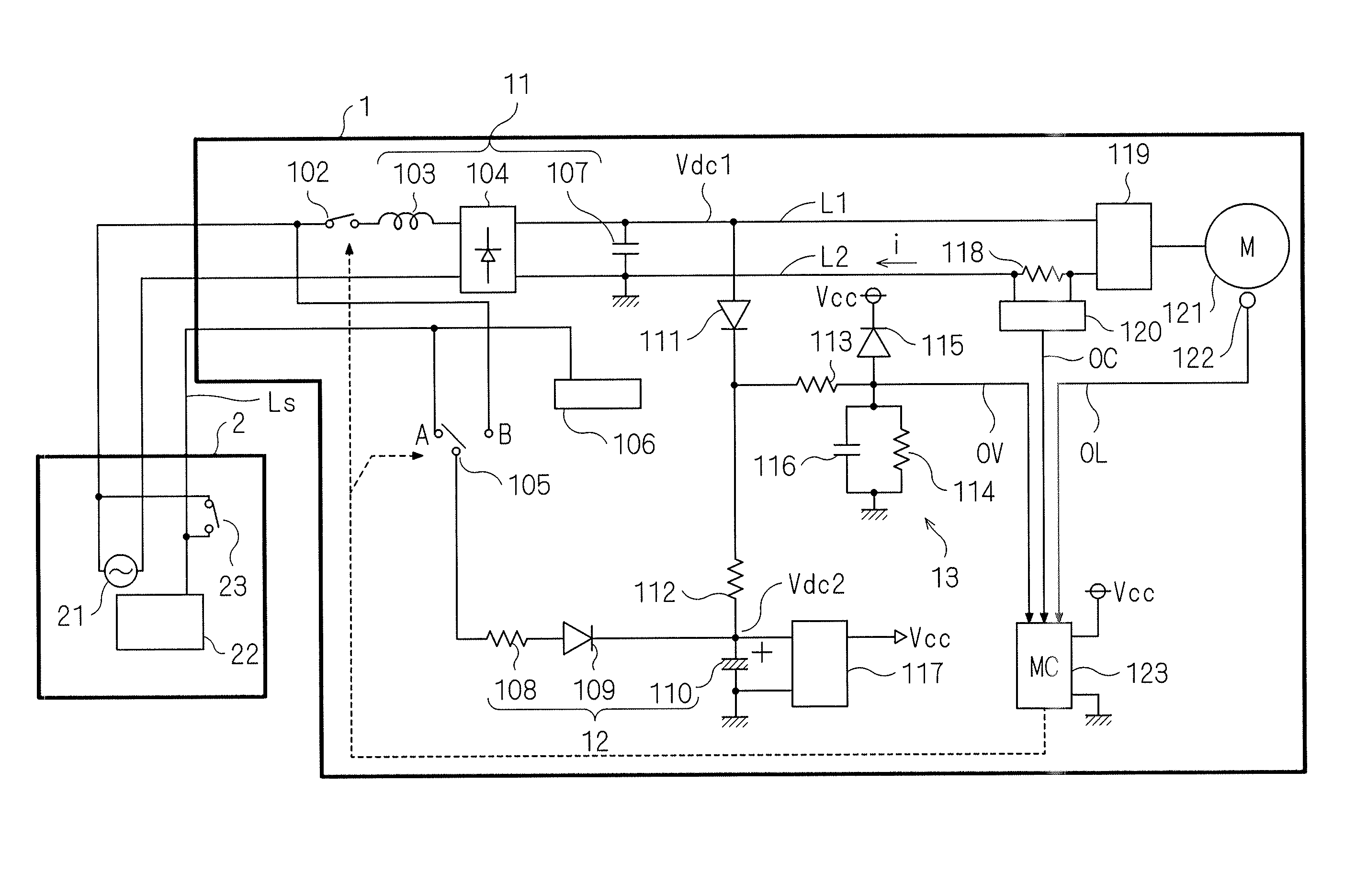
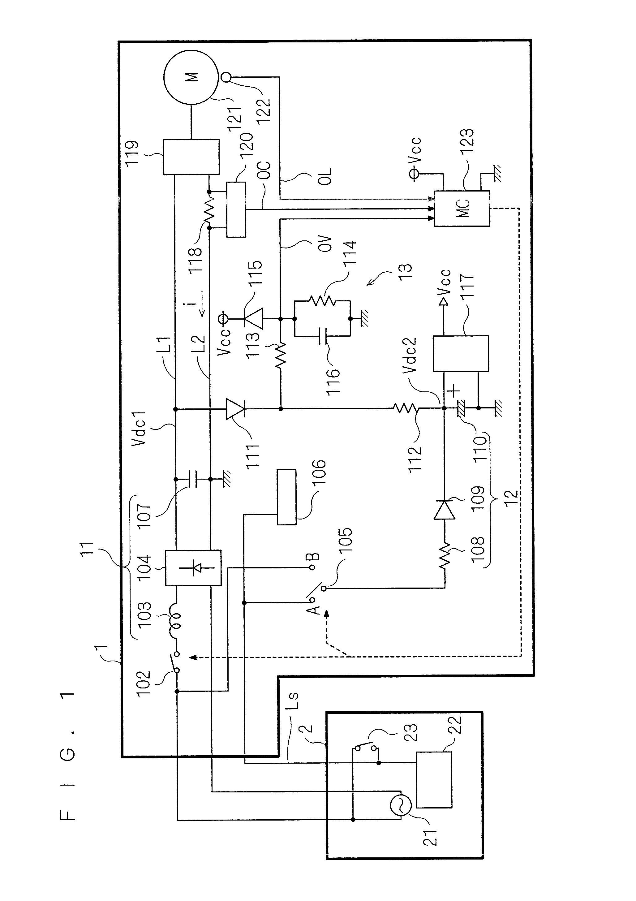
[0030]FIG. 1 is a circuit diagram showing part of an electrical configuration of an air conditioner including an outdoor unit 1 and an indoor unit 2. The indoor unit 2 includes an AC power supply 21, a communication circuit 22, and an indoor unit side switch 23. The AC power supply 21 supplies the outdoor unit 1 with an AC voltage.

[0031]While the AC power supply 21 can be actually obtained from a commercial power supply, here, it is expressed to be provided in the indoor unit 2. The communication circuit 22 is connected to the outdoor unit 1 through a communication line Ls and sends and receives signals transmitted between the indoor unit 2 and the outdoor unit 1. The indoor unit side switch 23 connects and cuts off the communication line Ls and the AC power supply 21 to and from each other.

[0032]The outdoor unit 1 includes components below. A main rectifier circuit 11 receives an AC voltage obtained from the AC power supply 21 through a first switch 102 to supply a main DC voltage ...


PUM


Abstract

Provided is a technique of detecting not only a main DC voltage but also an auxiliary DC voltage to protect a main rectifier circuit and an auxiliary rectifier circuit. A main power supply circuit drives a load. A main rectifier circuit receives an AC voltage through a first switch to supply the main power supply circuit with a main DC voltage. The first switch is turned off when an overcurrent flows through the main power supply circuit or the load is an overload for the main power supply circuit. A control circuit is supplied with operating power from an auxiliary power supply circuit. An auxiliary rectifier circuit receives the AC voltage while bypassing the first switch to supply the auxiliary power supply circuit with an auxiliary DC voltage. A DC voltage detection circuit detects the main DC voltage and the auxiliary DC voltage.

Description

TECHNICAL FIELD[0001]The present invention relates to a power supply apparatus and is applied to, for example, a power supply apparatus for use in an outdoor unit of an air conditioner.BACKGROUND ART[0002]An outdoor unit, which configures an air conditioner with an indoor unit, includes a compressor that compresses a refrigerant. The compressor is driven by a motor under the control of a microcomputer that controls the operation of the outdoor unit.[0003]The outdoor unit individually needs a power supply circuit (hereinafter, referred to as a “main power supply circuit”) such as an inverter for driving the motor and a power supply circuit (hereinafter, referred to as an “auxiliary power supply circuit”) that drives the microcomputer. This is because the motor may stop during the operation of the microcomputer in the outdoor unit.[0004]Thus, a DC voltage (hereinafter, referred to as a “main DC voltage”) to be supplied to the main power supply circuit and a DC voltage (hereinafter, re...

Claims


Application Information

Patent Timeline
IPC IPC(8): H02M5/458F24F11/33F24F11/46F24F11/49F24F11/62F24F11/64F24F11/86F24F11/88F24F11/89H02H3/08H02J1/00H02P29/02H02P29/62
CPCH02M5/4585H02H1/06H02H7/08H02H7/1252H02P29/032H02H3/08H02P29/02
Inventor TSUTSUI, YASUYUKIIMOTO, MITSURUSAKAE, NORIOJOUTAKI, KOUJIFUKADA, KEISUKESHOUJI, TETSUO
Owner DAIKIN IND LTD
Why Eureka
Try Eureka