Quadrature modulator

Active Publication Date: 2015-07-09
PANASONIC CORP
View PDF3 Cites 0 Cited by
  • Summary
  • Abstract
  • Description
  • Claims
  • Application Information

AI Technical Summary

Benefits of technology

[0014]Thus, the quadrature modulator according to one general aspect of the present disclosure is capable of combining outputs from a plurality o

Problems solved by technology

This amplification operation generally consumes large electric power.
Thus, in the digital power amplifier disclosed in Chao Lu, Hua Wang, C H Peng, Ankush Goel, SangWon Son, Paul Liang, Ali Hwang, and George Chein “A 24.7 dBm All-Digital RF Transmitter for Multimode Broadband Applications in 40 nm CMOS” ISSCC2013 SESSION 19/WIRELESS TRANSCEIVERS FOR SMART DEVICES/19.3, currents always flow, which results in

Method used


Image

  • Quadrature modulator
  • Quadrature modulator
  • Quadrature modulator

Examples


first embodiment

[0029]A quadrature modulator 100 according to a first embodiment of the present disclosure is described below.

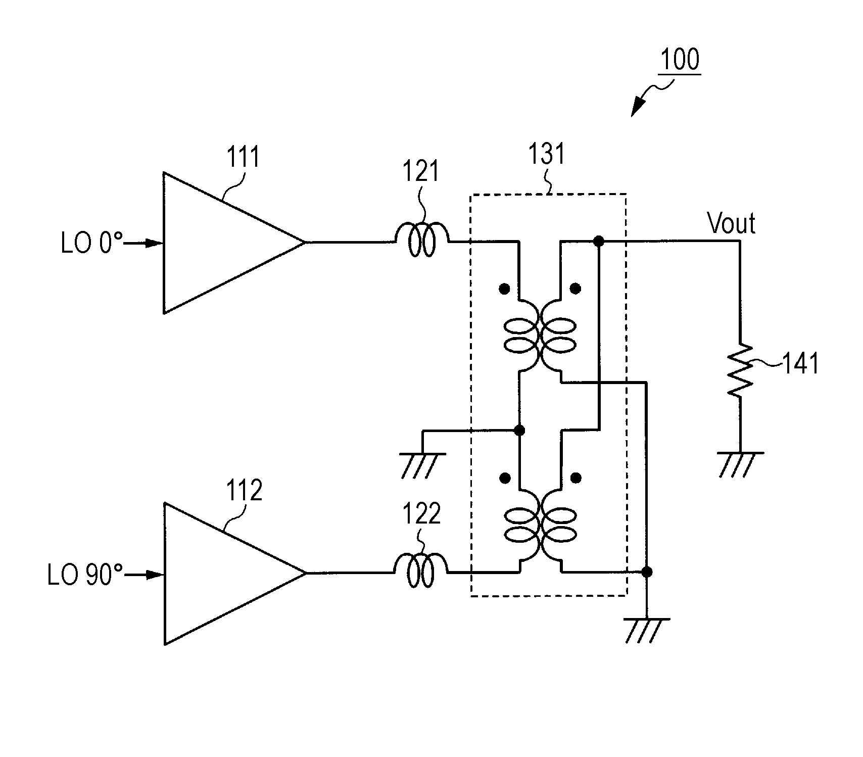
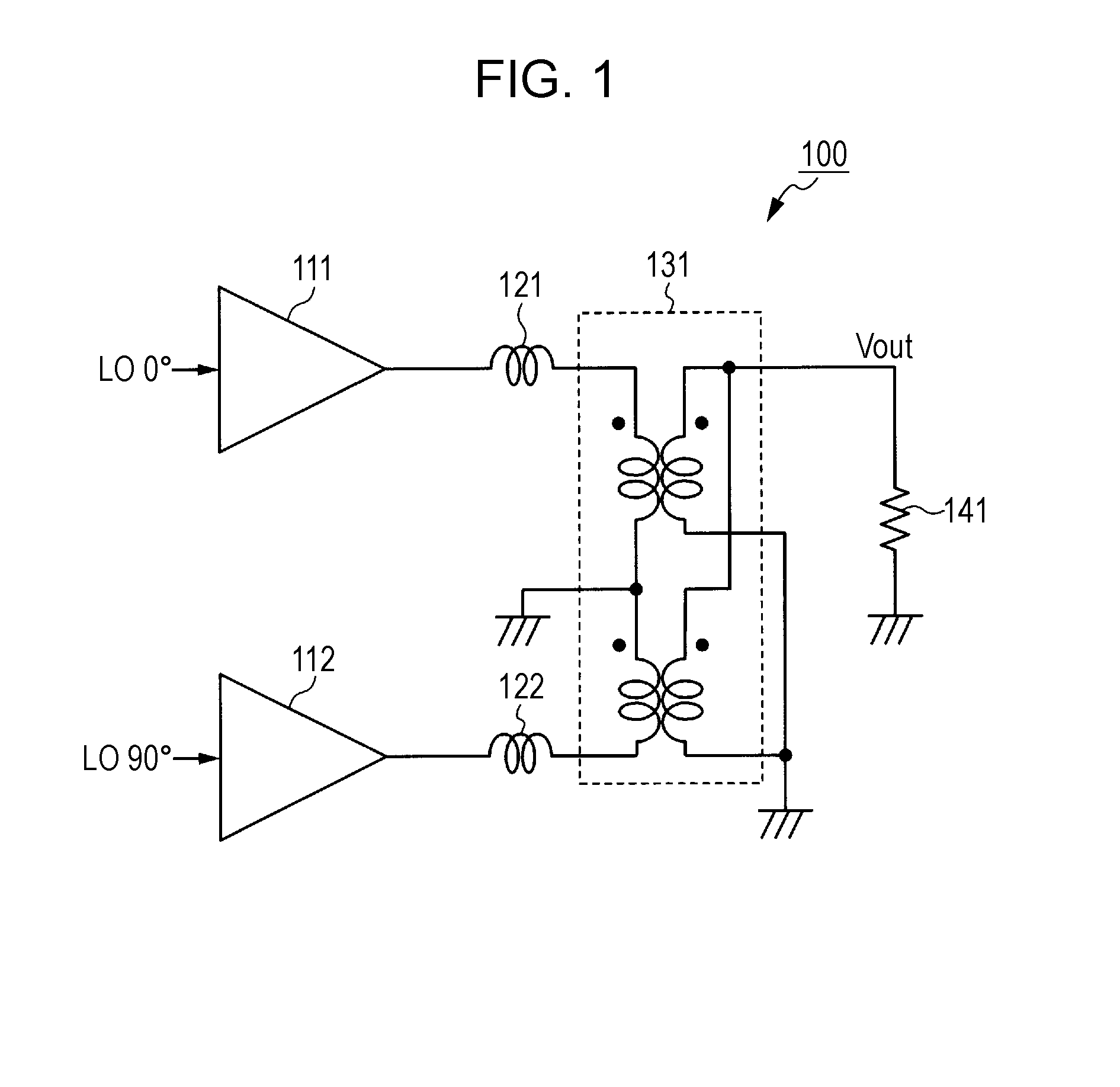
[0030]FIG. 1 is a diagram illustrating an example of a circuit configuration of the quadrature modulator 100 according to the first embodiment. As illustrated in FIG. 1, the quadrature modulator 100 includes amplifiers 111 and 112, inductors 121 and 122, and a balun 131.

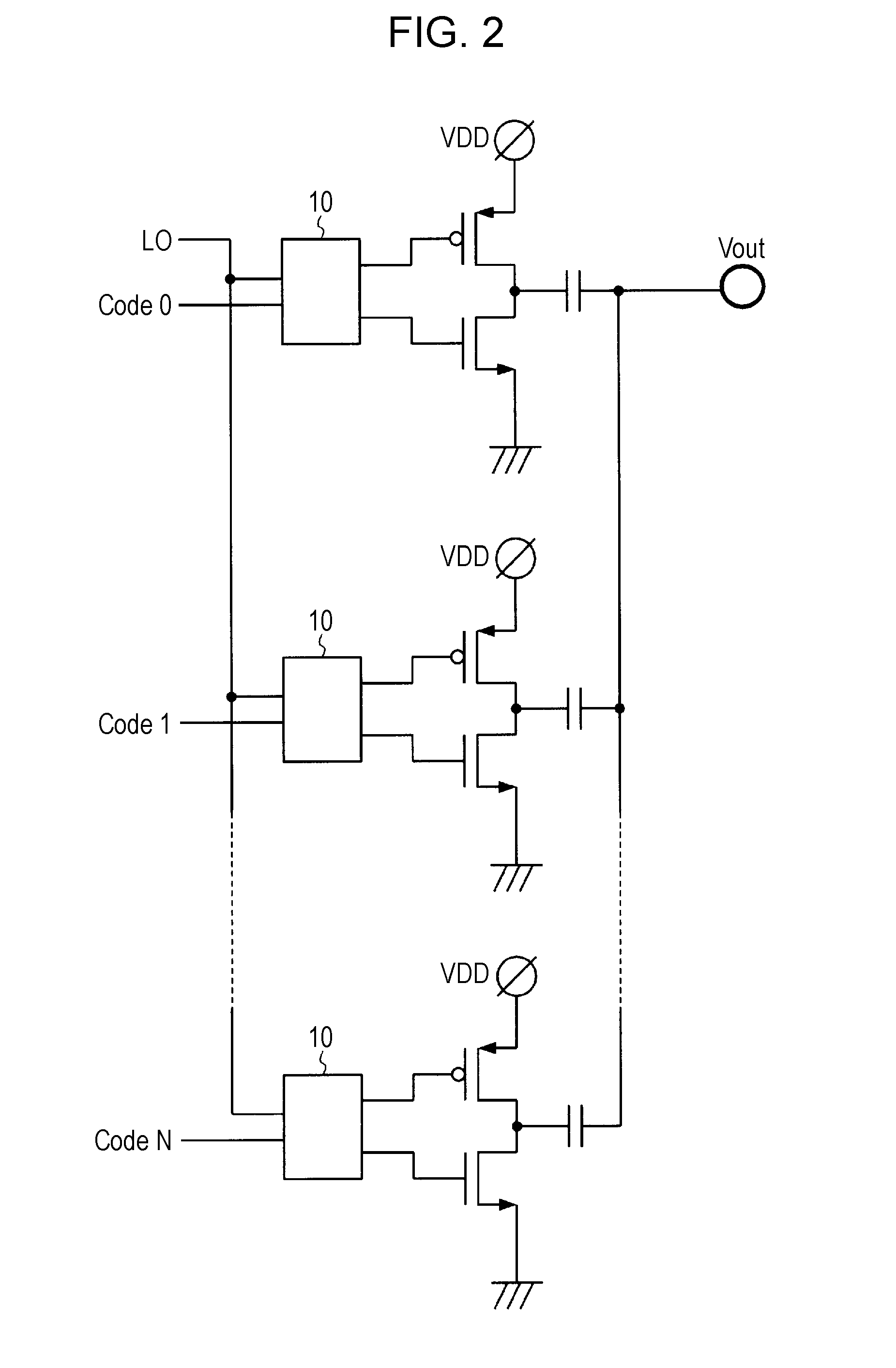
[0031]The amplifier 111 and the amplifier 112 each are a switched capacitor power amplifier (SCPA). In the quadrature modulator 100, a part including the amplifier 111 will be referred to as an I side, and a part including the amplifier 112 will be referred to as a Q side.

[0032]There is a relative phase difference of 90° between a high-frequency signal input to the amplifier 111 and a high-frequency signal input to the amplifier 112. That is, the phases of the two high-frequency signals are different by 90° such that the two high-frequency signals are orthogonal to each other. In FIG. 1, by way of example, a ...

second embodiment

[0052]A quadrature modulator 200 according to a second embodiment of the present disclosure is described below.

[0053]FIG. 8 is a diagram illustrating an example of a circuit configuration of the quadrature modulator 200 according to the second embodiment. As illustrated in FIG. 8, the quadrature modulator 200 includes amplifiers 211, 212, 213, and 214, inductors 221, 222, 223, and 224, and baluns 231 and 232.

[0054]The amplifiers 211 and 212 the inductors 221 and 222, and the balun 231 are the same as the amplifiers 111 and 112, the inductors 121 and 122, and the balun 131 described above in the first embodiment, and thus a further description thereof is omitted. However, note that one of the electrodes on the secondary side of the balun 231 is connected to the load 241 as in the first embodiment, but the other one of the electrodes is connected to one of two electrodes on the secondary side of the balun 232 unlike the first embodiment in which it is grounded.

[0055]Thus, the amplifie...

third embodiment

[0068]A quadrature modulator 300 according to a third embodiment of the present disclosure is described below.

[0069]FIG. 9 is a diagram illustrating an example of a circuit configuration of the quadrature modulator 300 according to the third embodiment. As illustrated in FIG. 9, the quadrature modulator 300 includes amplifiers 311, 312, 313, and 314, inductors 321, 322, 323, and 324, and baluns 331 and 332.

[0070]The amplifiers 311 to 314, the inductors 321 to 324, and the baluns 331 and 332 are respectively the same as the amplifiers 211 to 214, the inductors 221 to 224, and the baluns 231 and 232 described above in the second embodiment, and thus a further description thereof is omitted. However, the third embodiment is different from the second embodiment described above with reference to FIG. 8 in that a high-frequency signal with a phase of 180° is input to the amplifier 312, and a high-frequency signal with a phase of 90° is input to the amplifier 313.

[0071]That is, in the quad...


PUM


Abstract

A quadrature modulator includes a first switched capacitor power amplifier that amplifies a first high-frequency signal having a first phase, a second switched capacitor power amplifier that amplifies a second high-frequency signal having a second phase different from the first phase, a first combiner which includes at least one pair of winding wires that are magnetically coupled to each other, one winding wire in one pair being disposed on a primary side to which the amplified first high-frequency signal and the amplified second high-frequency signal are separately input and the other winding wire in the one pair being disposed on a secondary side, the first combiner combining the input amplified first high-frequency signal and the input amplified second high-frequency signal to generate a quadrature modulation signal from the secondary side, a first inductor disposed between the first switched capacitor power amplifier and the primary side of the first combiner, and a second inductor disposed between the second switched capacitor power amplifier and the primary side of the first combiner.

Description

BACKGROUND[0001]1. Technical Field[0002]The present disclosure relates to a power amplifier, and more particularly, to a quadrature modulator that performs quadrature modulation using a switched capacitor power amplifier.[0003]2. Description of the Related Art[0004]A power amplifier amplifies a weak input signal and outputs a resultant amplified signal to provide a signal with a high strength necessary in wireless communication. This amplification operation generally consumes large electric power. In particular, in a wireless communication apparatus (for example, a portable telephone or the like) driven by a battery, the power consumption has a significant influence on a maximum run time, and thus it is necessary to increase a power efficiency to reduce the power consumption.[0005]One known method of increasing the power efficiency is to use a Class-D power amplifier. The Class-D power amplifier is an amplifier that operates using saturation of a transistor such that a current is pa...

Claims


Application Information

Patent Timeline
IPC IPC(8): H03F1/02H04L25/03H03F3/00H04L27/26H03F3/19H03F3/217
CPCH03F1/0205H03F3/19H03F3/2178H03F3/005H04L2025/03414H04L25/03343H03F2203/21142H03F2200/336H04L27/2614H04L27/36H03F1/56H03F3/195H03F3/2171H03F3/245H03F2200/09H03F2200/387H03F2200/537H03F2200/541H03C1/12H03C3/40H03C2200/0058H03C1/36
Inventor KUMAGAWA, MASAHIROHIRAI, YOSHITO
Owner PANASONIC CORP
Why Eureka
Try Eureka