Hydraulic suspension damper with a position dependent damping assembly

Active Publication Date: 2015-07-23
BEIJINGWEST INDUSTRIES
View PDF9 Cites 7 Cited by
  • Summary
  • Abstract
  • Description
  • Claims
  • Application Information

AI Technical Summary

Benefits of technology

[0022]The bumper may prevent against eventual engaging the free upper end of the second spring with components of the rebound valve of the piston assembly and may also stabilize the second spring thus reducing possible

Problems solved by technology

Unfortunately, this neutral position of a piston varies during daily vehicle exploitation.
In both cases this shift of a neutral position may lead to a situation in which displacement of a piston will exceed its assumed stroke limits leading to a suspension closure or jounce bumper engagement, which in turn affects safety, comfort, durability and noise issues.
On the other hand, even for a nominally loaded vehicle, displacement of a piston may also exceed its assumed stroke limits, for example while driving on a rough road or during a road bump.
Such compression s

Method used


Image

  • Hydraulic suspension damper with a position dependent damping assembly
  • Hydraulic suspension damper with a position dependent damping assembly
  • Hydraulic suspension damper with a position dependent damping assembly

Examples


Embodiment Construction

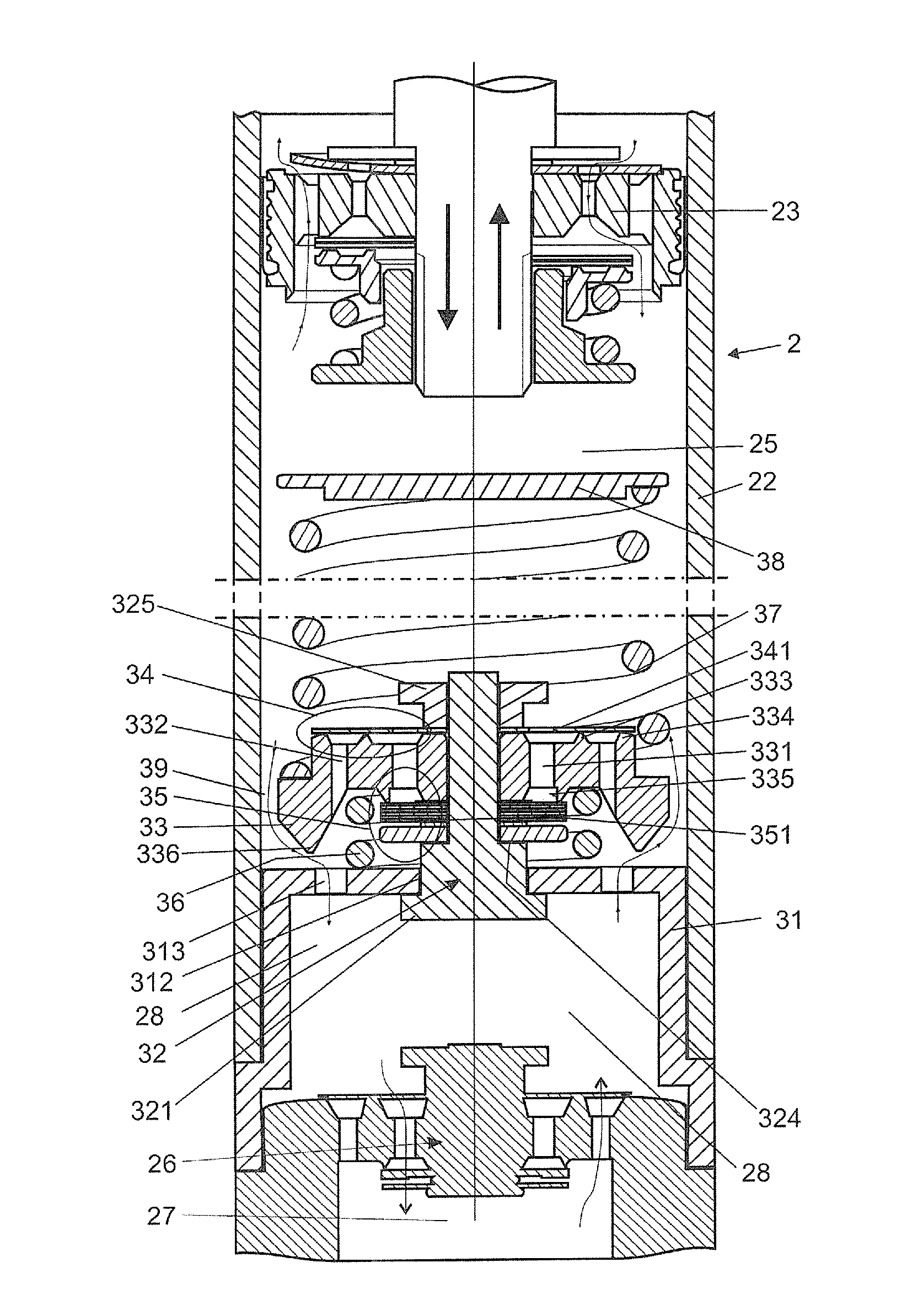
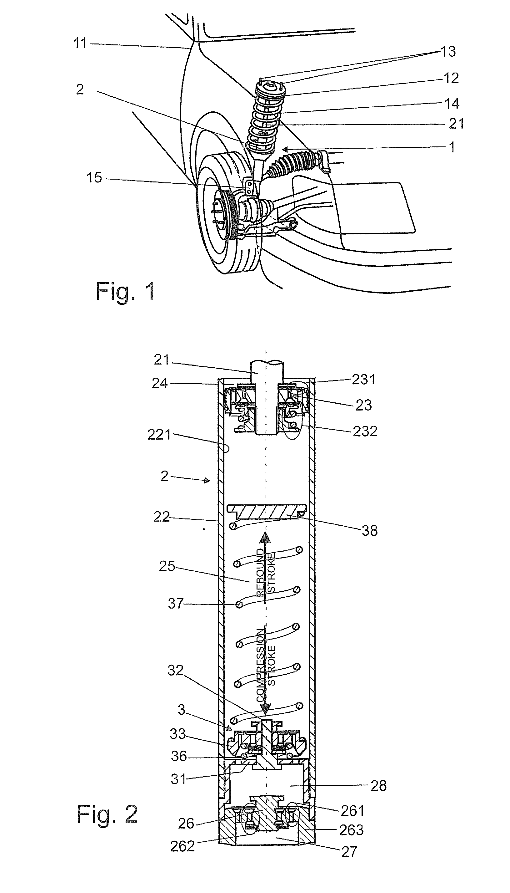
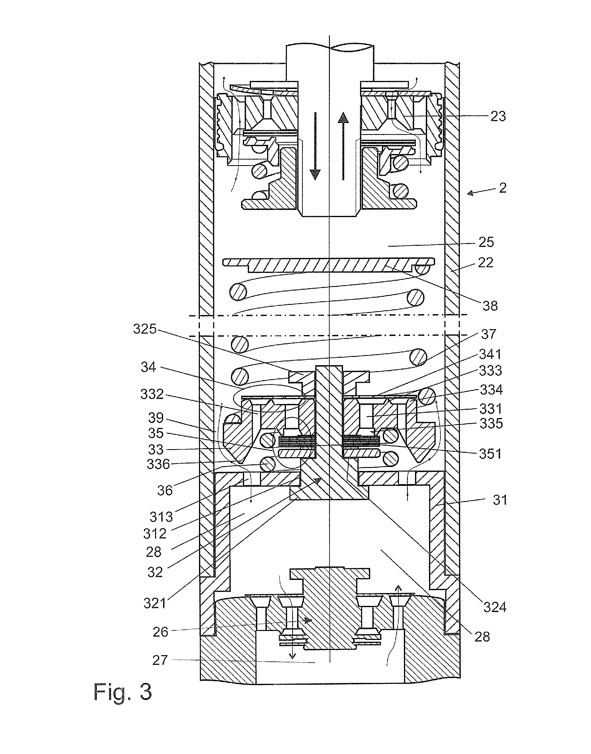
[0037]FIG. 1 schematically illustrates a fragment of an exemplary vehicle suspension 1 attached to a vehicle chassis 11 by means of a top mount 12 and a number of screws 13 disposed on the periphery of the upper surface of the top mount 12. The top mount 12 is connected to a coil spring 14 and a rod 21 of a mono- or twin-tube hydraulic damper 2. Inside a tube of the damper 2 a piston assembly attached to the rod 21 led outside the tube is slidably disposed. At the other end the damper tube is connected to the steering knuckle 15 supporting the vehicle wheel.

[0038]A hydraulic damper 2 shown in part in FIG. 2 is an example of a twin-tube damper that may be employed in a vehicle suspension 1 presented in FIG. 1. Schematically depicted movable piston assembly 23 makes a sliding fit with the inner surface 221 of the tube 22, dividing the tube 22 into a rebound chamber 24 (here above the piston assembly) and a compression chamber 25 (here below the piston assembly). At one end the piston ...


PUM


Abstract

Provided is a hydraulic damper with a position dependent valve assembly (3) to prevent abrupt stop of a piston at the end of the compression stroke. The position dependent valve assembly (3) comprises a supporting member (31) partitioning damper (2) internal tube (22) and provided with an axial opening (312), an axial member (32) disposed slidably within said axial opening (312) of said supporting member (31), a rigid body (33) fixed on said axial member (32), a compression stroke disc assembly (35) and a rebound stroke disc assembly (34) fixed on said axial member (32).

Description

[0001]The present invention relates to a hydraulic damper, in particular a motor vehicle suspension damper.BACKGROUND OF THE INVENTION[0002]Hydraulic suspension dampers typically comprise a tube filled with working liquid, inside of which a slidable piston is placed. The piston is attached to a piston rod led outside the damper through a piston rod guide, and has a form of a piston assembly comprising rebound and compression valves, which control the flow of working liquid passing through the piston during the rebound and the compression stroke of the damper. Some dampers also comprise a base (bottom) assembly with separate rebound and compression valves controlling the flow of working liquid passing in and out of the additional compensation chamber.[0003]Typically, damping force generated by a damper is related to the speed of the piston and motor vehicle suspensions are designed in order to provide unobstructed displacement of the piston up and down within a tube with respect to s...

Claims


Application Information

Patent Timeline
IPC IPC(8): F16F9/58F16F9/348F16F9/34F16F9/18
CPCF16F9/585F16F9/34F16F9/3488F16F9/18F16F9/49F16F9/48
Inventor KUS, PAWEL EDWARDGRZESIK, RADOSLAW PAWELFLACHT, PIOTR ANDRZEJFIREK, LUKASZ KAROL
Owner BEIJINGWEST INDUSTRIES
Why Eureka
Try Eureka