Light source device and projector

a light source device and projector technology, applied in the field of light source devices and projectors, can solve the problems of insufficient improvement effect of fluorescence efficiency, failure to be used as illumination light, and confined remaining components of the device, so as to improve fluorescence efficiency and improve projection image brightness.

Active Publication Date: 2015-07-23
SEIKO EPSON CORP
View PDF8 Cites 15 Cited by
  • Summary
  • Abstract
  • Description
  • Claims
  • Application Information

AI Technical Summary

Benefits of technology

[0028]According to such a projector as described above, by using the light source device with the efficiency of the fluorescence improved as the illumination device, even if the light intensity of the excitation light with which the phosphor layer is irradiated is reduced, the light intensity substantially the same in luminance as in the related art can be obtained to thereby keep the brightness of the projection image in substantially the same level as in the related art. Further, in the case of irradiating the phosphor layer with the excitation light substantially the same in light intensity as in the related art, since the brightness of the light source device can be improved compared to the related art, the brightness of the projection image can be improved.

Problems solved by technology

However, an experiment having been conducted by the inventors shows the fact that although a part of the light having returned to the inside of the light transmissive member is emitted from an upper surface of the light transmissive member, the remaining component thereof is confined in the inside of the light transmissive member, and fails to be used as the light for illumination.
Therefore, sufficient improvement effect in the efficiency of the fluorescence is not obtained.

Method used


Image

  • Light source device and projector
  • Light source device and projector
  • Light source device and projector

Examples


first embodiment

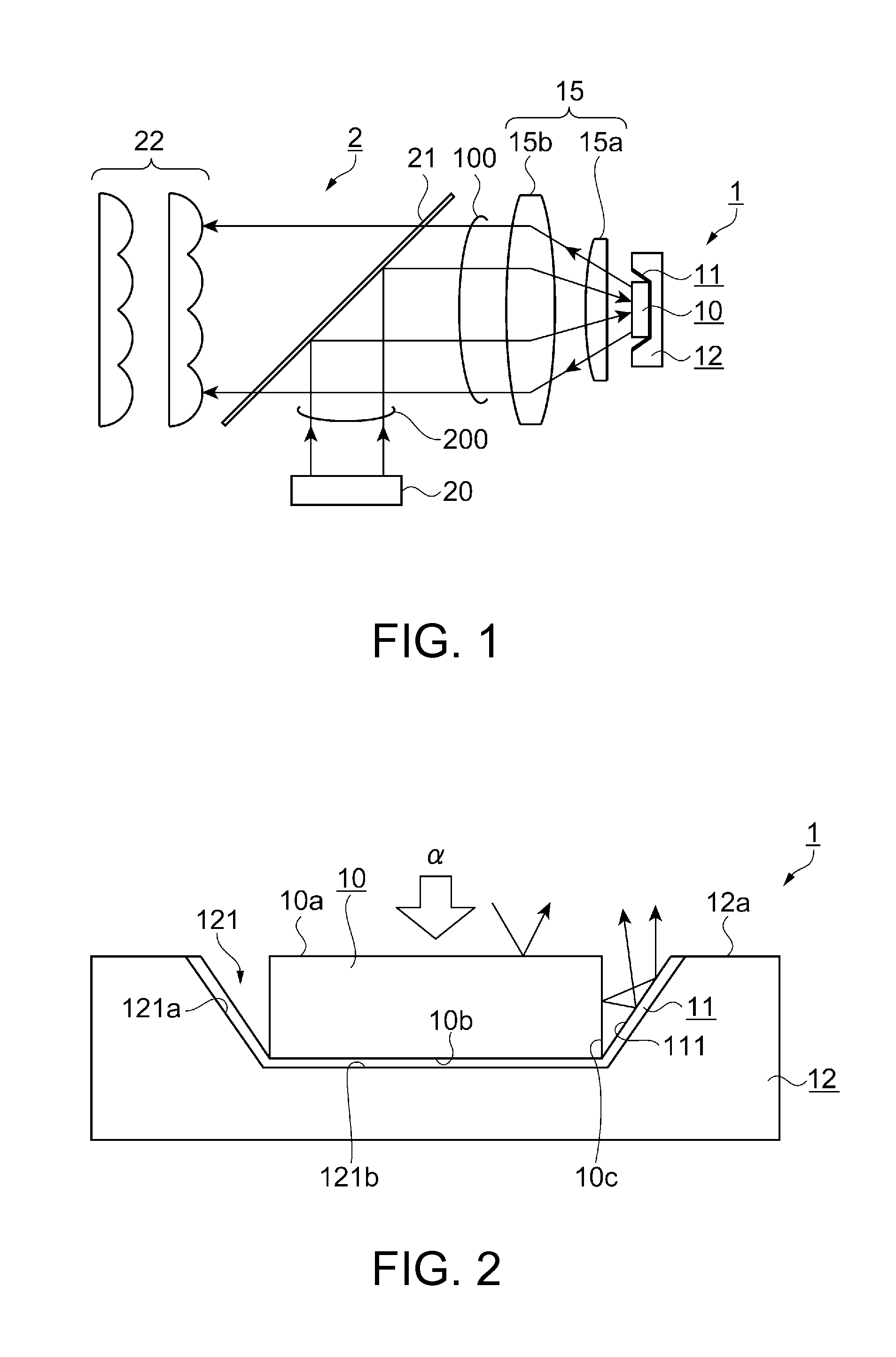
[0040]FIG. 1 is a schematic configuration diagram showing an illumination device 2 using a light source device 1 according to a first embodiment. The configuration of the illumination device 2 (the light source device 1) will be explained with reference to FIG. 1.

[0041]As shown in FIG. 1, the light source device 1 is provided with a phosphor layer 10, a reflecting member 11, a substrate 12, and a collimating optical system 15. Further, the illumination device 2 is provided with an excitation light source 20, a dichroic mirror 21, a lens array 22, and so on in addition to the light source device 1.

[0042]The phosphor layer 10 generates and then emits the fluorescence in response to irradiation with the excitation light. It should be noted that the details of the phosphor layer 10 will be described later.

[0043]The excitation light source 20 irradiates the phosphor layer 10 with the excitation light. As the excitation light source 20, a laser source for emitting blue light (having a wav...

second embodiment

[0084]FIG. 4 is a cross-sectional view showing a configuration of a light source device 1A according to a second embodiment. The configuration and an operation of the light source device 1A will be explained with reference to FIG. 4.

[0085]As shown in FIG. 4, the light source device 1A according to the present embodiment is different in the cross-sectional shape of the reflecting member from the light source device 1 according to the first embodiment. The rest of the configuration is substantially the same as that of the first embodiment. Therefore, the constituents substantially the same as those of the first embodiment will be denoted with the same reference symbols as in the first embodiment, and the explanation thereof will be omitted.

[0086]In order to improve the usage efficiency of the light, which has been emitted from the light source device, in the optical system in the posterior stage, it is preferable to make the light emitting area small. To that end, it is possible to de...

third embodiment

[0091]FIGS. 5A and 5B are cross-sectional views showing a configuration of a light source device 1B according to the third embodiment of the invention, wherein FIG. 5A is a cross-sectional view, and FIG. 5B is an enlarged view of the cross-sectional view. The configuration and an operation of the light source device 1B will be explained with reference to FIGS. 5A and 5B.

[0092]As shown in FIGS. 5A and 5B, the light source device 1B according to the present embodiment is different from the light source device 1 according to the first embodiment in that alight transmissive member 13 higher in refractive index than air is disposed between the side surface 10c of the phosphor layer 10 and the reflecting member 11. The rest of the configuration is substantially the same as that of the first embodiment. Therefore, the constituents substantially the same as those of the first embodiment will be denoted with the same reference symbols as in the first embodiment, and the explanation thereof w...


PUM


Abstract

A light source device includes a phosphor layer having a side surface, a bottom surface, and an upper surface opposed to the bottom surface, a substrate disposed on the bottom surface side of the phosphor layer, and a reflecting member disposed outside the phosphor layer. The phosphor layer generates fluorescence in response to irradiation with excitation light. The fluorescence generated in the phosphor layer is emitted from the upper surface and the side surface. The fluorescence emitted from the side surface enters the reflecting member.

Description

BACKGROUND[0001]1. Technical Field[0002]The present invention relates to a light source device and a projector equipped with the light source device.[0003]2. Related Art[0004]In the past, there has been known a projector, which modulates light emitted from a light source device in accordance with image information, and then projects the light. In such a projector, there has been used a discharge light source device as the light source device in the past. However, in recent years, the chance of using a light emitting device such as a light emitting diode (LED) or a semiconductor laser has increased. Further, there has been used a light source device for performing wavelength conversion on the light from the semiconductor laser or the like using a fluorescent material.[0005]JP-A-2005-277331 (Document 1) discloses a light emitting device provided with a light transmissive member including a fluorescent material and a reflecting member as a reflecting surface in order to improve the eff...

Claims


Application Information

Patent Timeline
Patent Type & Authority Applications(United States)
IPC IPC(8): F21V13/08F21V9/16G03B21/20
CPCF21V13/08F21V9/16G03B21/204G03B21/2066H01L33/486H01L33/505H01L33/60
Inventor ARAKAWA, OSAMU
Owner SEIKO EPSON CORP
Why Eureka
Try Eureka