Polarization Diverse Wavelength Selective Switch

a wavelength selective switch and wavelength technology, applied in multiplex communication, optical elements, instruments, etc., can solve the problems of directivity issues, limit the number and location of possible ports and the functionality of the device, and the device's siz

Active Publication Date: 2015-07-23
II VI DELAWARE INC
View PDF8 Cites 25 Cited by
  • Summary
  • Abstract
  • Description
  • Claims
  • Application Information

AI Technical Summary

Benefits of technology

[0010]It is an object of the invention, in its prefe...

Problems solved by technology

However, constraints on the size of the device generally place limits on the number and location of possible ports and the functionality of the device.
Further, with increased port numbers, directivity issues become more prominent as the number of possible switching states gives rise to undesired connectivity between pairs of ports.
Such undesired links become more common as the number of ports in a switching device increases and also as the number of network switching points increases, particularly in networks utilizing bidirectional dual source WSS de...

Method used


Image

  • Polarization Diverse Wavelength Selective Switch
  • Polarization Diverse Wavelength Selective Switch
  • Polarization Diverse Wavelength Selective Switch

Examples


second embodiment

[0142]Referring now to FIG. 14, there is illustrated a second embodiment beam confining module 108. Module 108 includes a coupling prism 114.

[0143]To confine the beams from the two sources, beam 81 from Source A is directed onto a first reflective surface 116 of prism 114 which reflects beam 81 at an angle substantially 90° from the input direction. Beam 89 from Source B is directed onto a second reflective surface 118 of prism 114 and is also reflected at an angle substantially 90° to the input direction. Reflective surfaces 116 and 118 are disposed substantially parallel with each other but are spatially separated. The reflection of beam 81 occurs at a longitudinally separate location from that of beam 89 and, upon reflection, this separation translates to a controlled transverse separation.

[0144]The focal point from focusing lens 37 of module 97 is located at surface 116 and the focal point from lens 37 of module 99 is located on transmissive surface 112. In other embodiments, th...

third embodiment

[0146]Referring to FIG. 15, there is illustrated a third embodiment beam confining module 120. Module 120 operates in substantially the same manner as module 108 of FIG. 12 but is positioned to output confined parallel beams 81 and 89 at an angle greater than 90° to the input direction. In various embodiments, beams 81 and 89 from sources A and B are able to be confined to arbitrary spatial offsets and directed at arbitrary angles by varying the orientation and / or distance between surfaces 116 and 118.

[0147]Although, beams 81 and89 are illustrated as having an input spatial separation of 3 mm in FIGS. 14 and 15, it will be appreciated that this spatial separation is exemplary and dependent upon the particular optical system. In other embodiments, beams 81 and 89 are input from sources A and B with different spacings.

[0148]The fiber ports, polarizing modules 97 and 99 and beam confining module 101 collectively define a “front end” of WSS device 75. The “back end” is defined by the sw...


PUM


Abstract

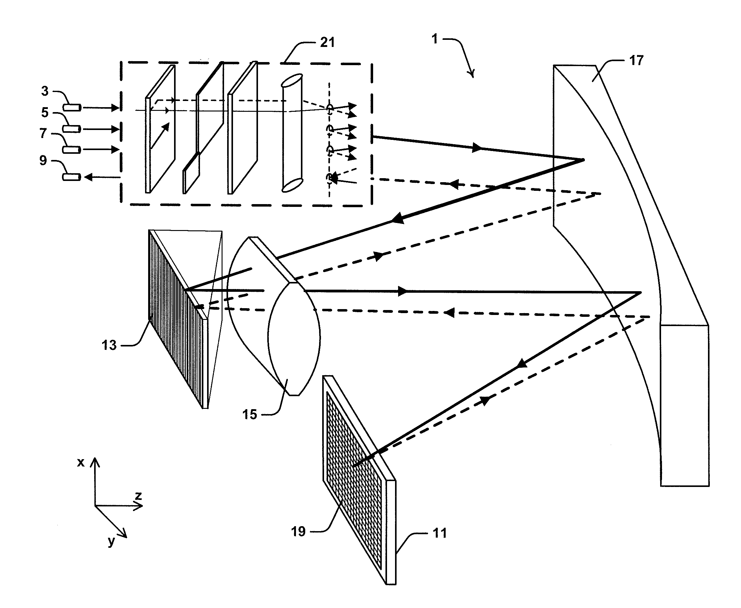
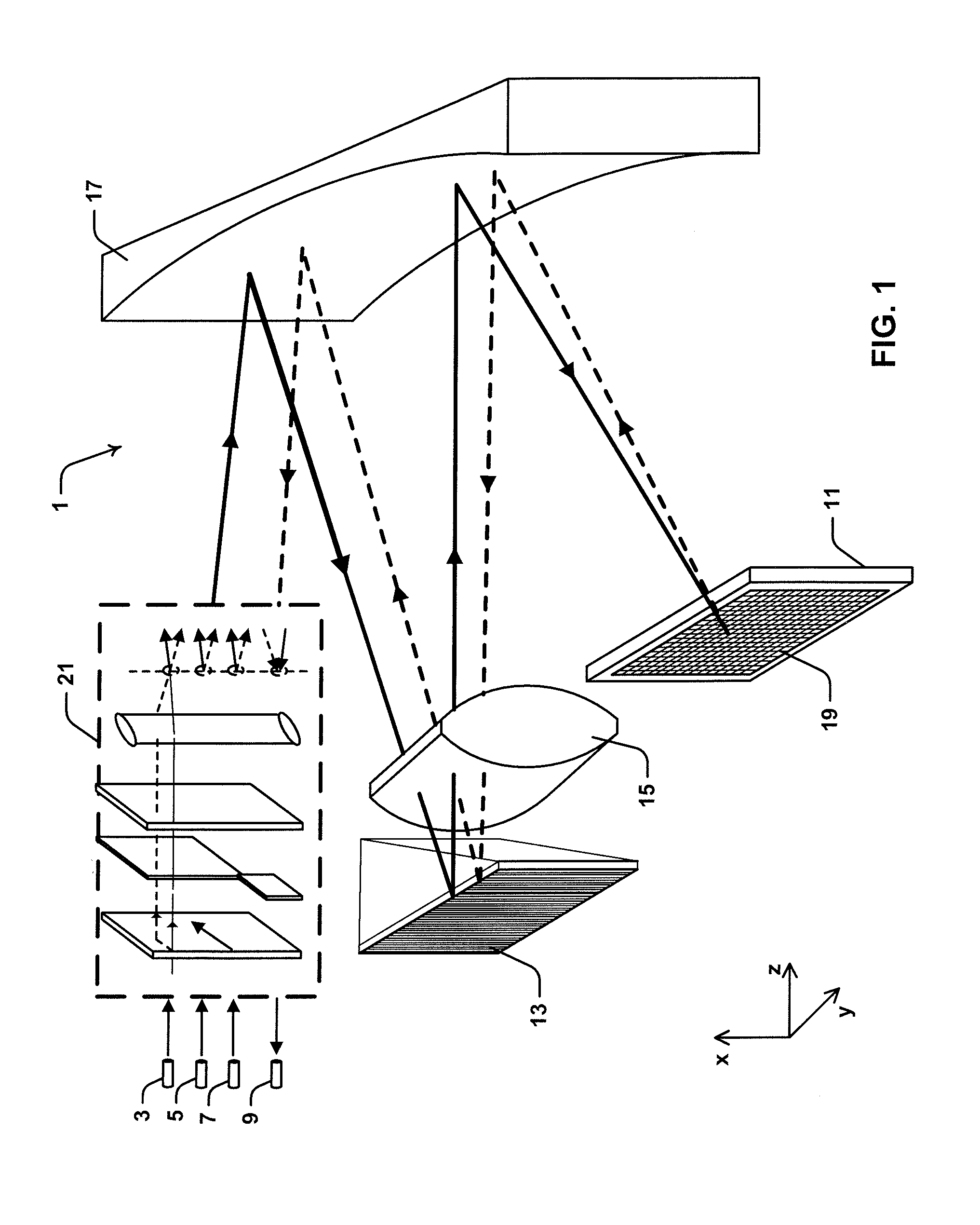
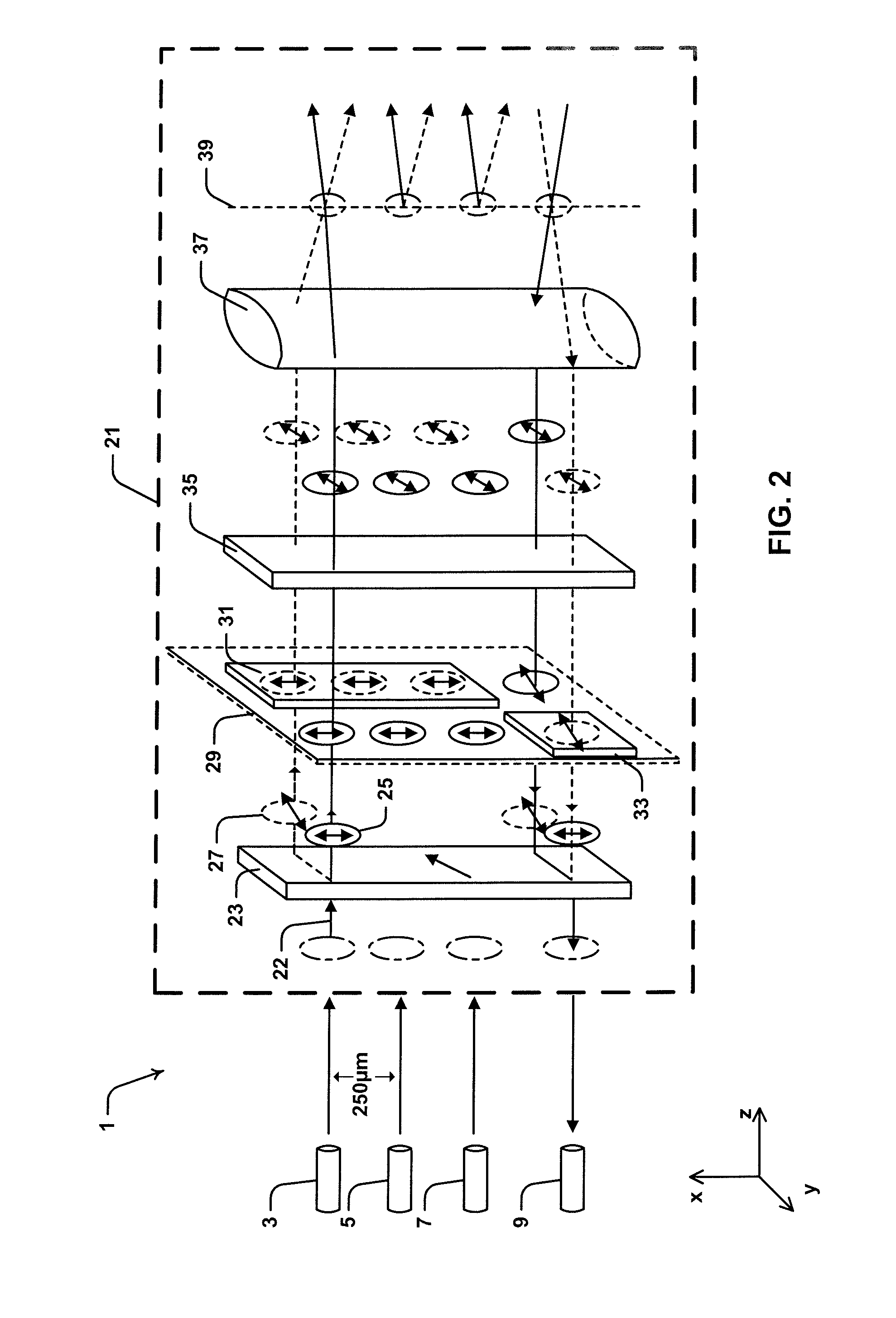
Described herein is a wavelength selective switch (WSS) type optical switching device (1) configured for switching input optical beams from input optical fiber ports (3, 5 and 7) to an output optical fiber port (9). Device (1) includes a wavelength dispersive grism element (13) for spatially dispersing the individual wavelength channels from an input optical beam in the direction of a second axis (y-axis). The optical beams propagate from input ports (3, 5 and 7) in a forward direction and are reflected from a liquid crystal on silicon (LCOS) device (11) in a return direction to output port (9). The input optical beams are transmitted through a port selecting module (21), which provides polarization diversity to device (1) and provides capability to restrict optical beams returning from LCOS device (11) from being coupled back into input ports (3, 5 and 7).

Description

CROSS REFERENCE TO RELATED APPLICATION SECTION[0001]The present application claims priority to U.S. Provisional Patent Application No. 61 / 673,580, filed on Jul. 19, 2012, entitled “Polarization Diverse Wavelength Selective Switch.” The entire content of U.S. Provisional Patent Application No. 61 / 673,580 is herein incorporated by reference.FIELD OF THE INVENTION[0002]The present invention relates to an optical switching device and in particular to a wavelength selective switch (WSS) implementing polarization manipulation optics. While some embodiments will be described herein with particular reference to that application, it will be appreciated that the invention is not limited to such a field of use, and is applicable in broader contexts.BACKGROUND[0003]Any discussion of the background art throughout the specification should in no way be considered as an admission that such art is widely known or forms part of common general knowledge in the field.[0004]With the development of more ...

Claims


Application Information

Patent Timeline
IPC IPC(8): H04Q11/00H04J14/02H04J14/06
CPCH04Q11/0003H04J14/06H04Q2011/0035H04Q11/0005H04Q2011/0016H04J14/0212G02B6/3512G02B6/356G02B6/29373G02B6/2931G02B6/3556H04J14/0221H04Q2011/0039
Inventor FRISKEN, STEVEN JAMES
Owner II VI DELAWARE INC
Why Eureka
Try Eureka