
Coating device

a coating material and vibration technology, applied in the field of coating devices, can solve the problems of discomfort and damage to the physique of therapists, the inability of beauty care equipment and/or medical auxiliary equipment to improve the efficiency of beauty care equipment and/or medical auxiliary equipment, and the inability to provide a simple vibration effect, etc., to achieve convenient and convenient performance, efficient absorbing, and facilitate the permeation and absorption of coating materials

Active Publication Date: 2015-07-30
WU CHUN HUNG
View PDF5 Cites 1 Cited by
  • Summary
  • Abstract
  • Description
  • Claims
  • Application Information

AI Technical Summary

Benefits of technology

The patent describes a coating device that uses thermoelectric cooling to efficiently apply coating material to a target object. The device has a receiving space where the coating material is heated and then cooled by a cooling region, resulting in the material being absorbed by the surface of the object. The device also has a storage groove for feeding the coating material and does not require the user to touch it. The device circulates hot and cold flows to facilitate the absorption of the coating material onto the object. The detachable components make it easy to clean and replace the device. The technical effects are an efficient and convenient method for applying coatings to objects.

Problems solved by technology

However, the conventional beauty care apparatuses can only provide a simple vibration effect and perform limited effect for the skin to absorb skin care products.
Therefore, how to improve the efficiency of the beauty care apparatuses and / or the medical auxiliary apparatuses becomes an issue for related personnel.
The physical contact might result in the discomfort and damaging of the therapist's physique.
In addition, carrying out the application of the beauty products without any auxiliary equipment is physically demanding, time consuming and less hygienic.

Method used


Image

  • Coating device
  • Coating device
  • Coating device

Examples


Embodiment Construction

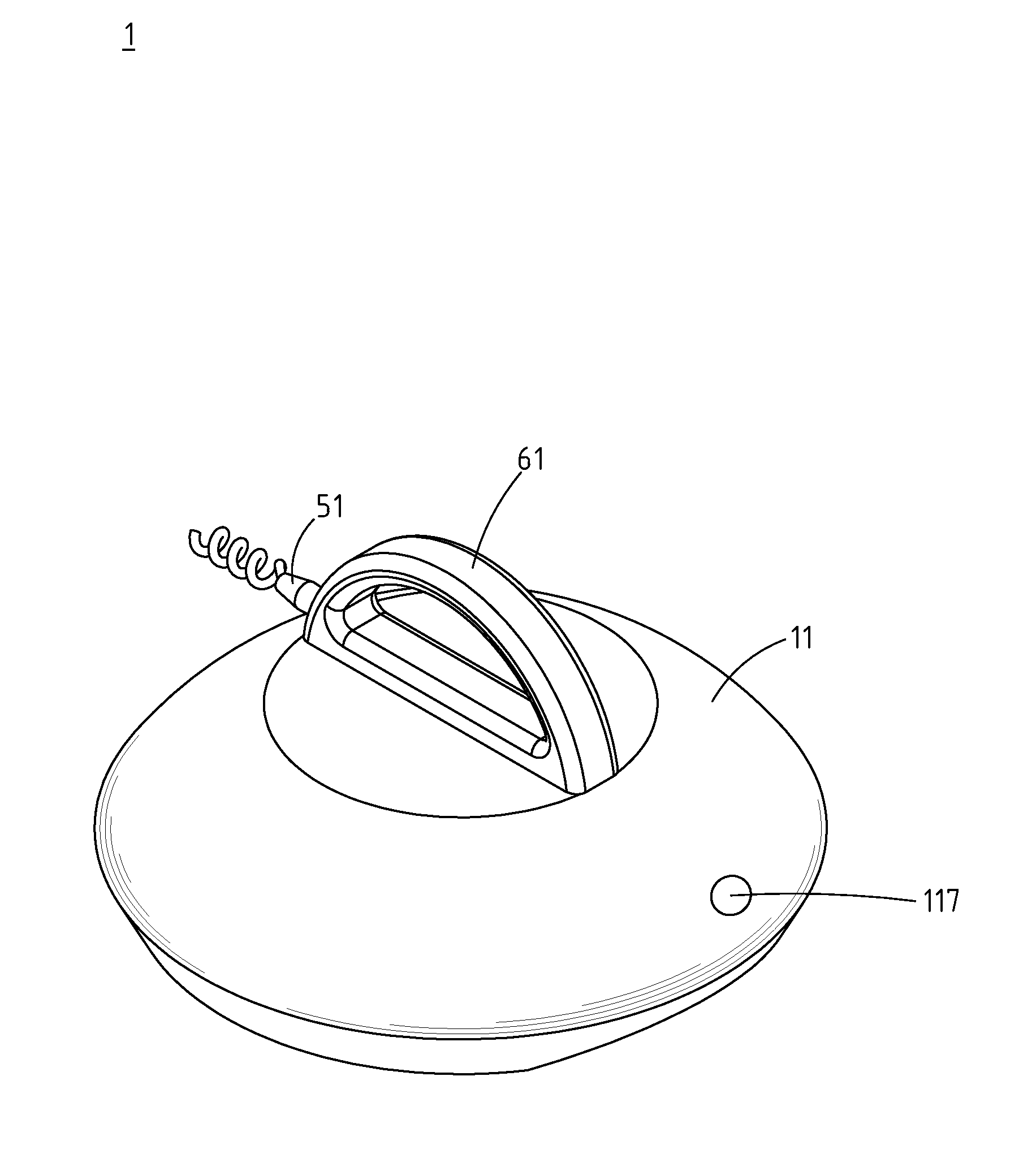
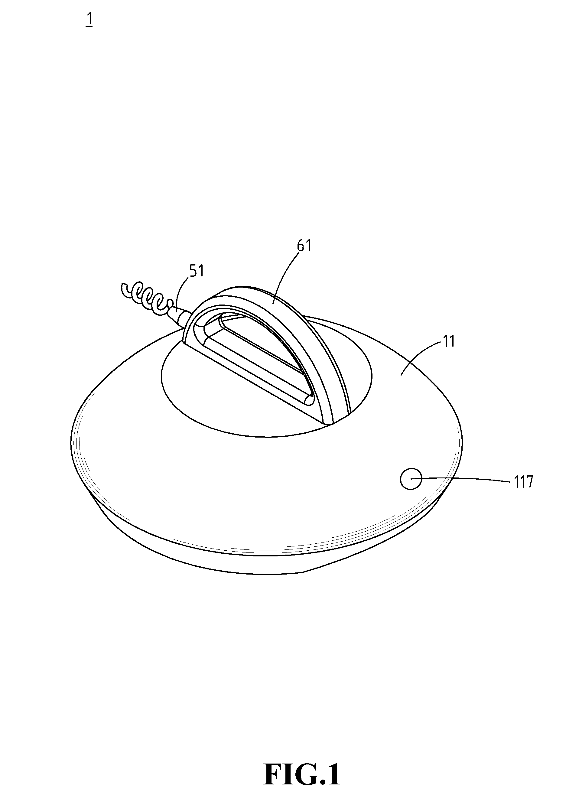
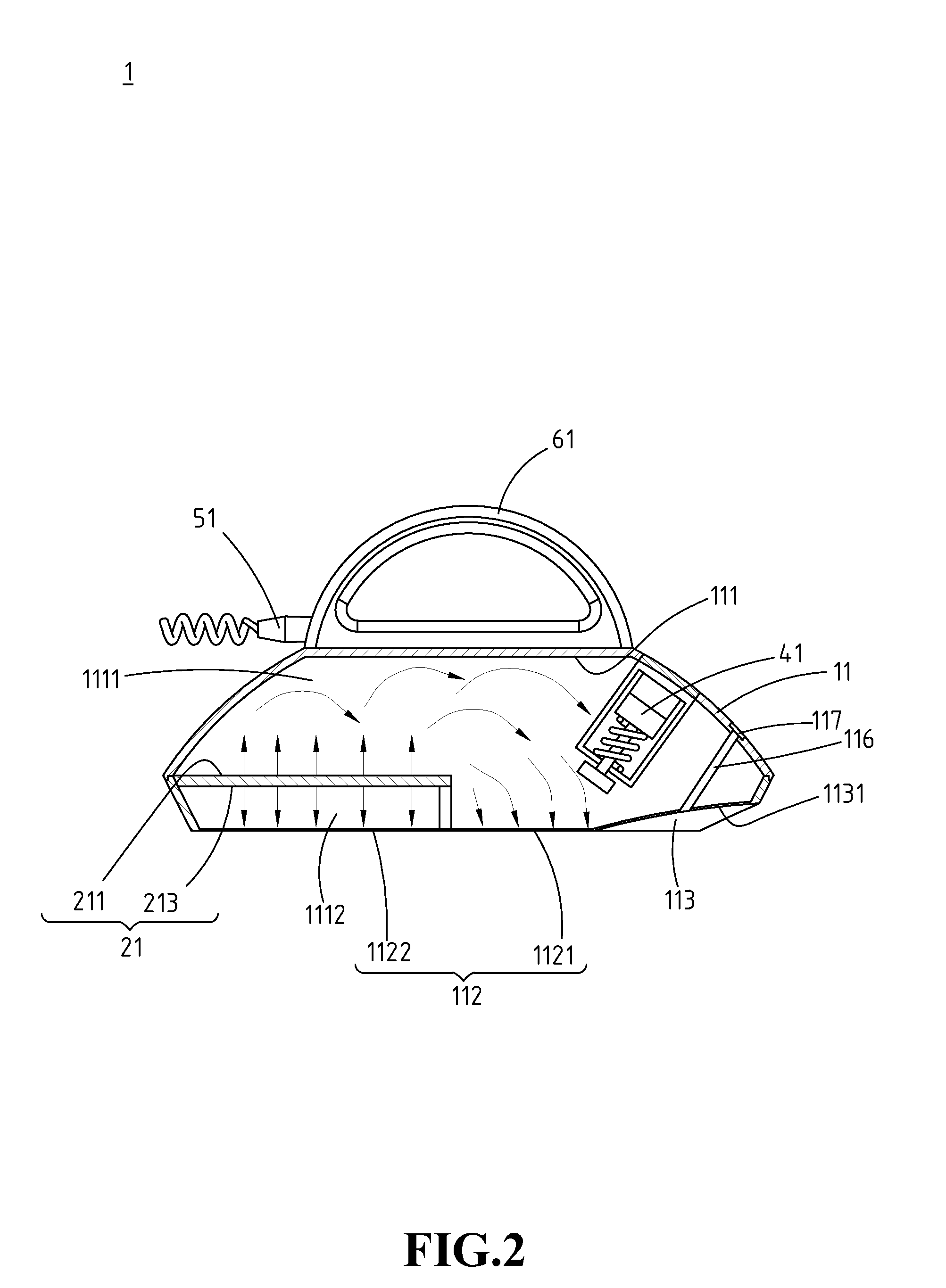
[0023]Please refer to FIG. 1 to FIG. 3, illustrating an exemplary embodiment of a coating device 1 according to the instant disclosure. FIG. 1 is a perspective view, FIG. 2 is a lateral sectional view, and FIG. 3 is a bottom view of the exemplary embodiment of the coating device 1 according to the instant disclosure. Here, the coating device 1 is adapted to generate a temperature difference for applying a coating material 91 on the surface of a target object. The target object may be user's skin, woods, textile. Taking the user's skin as an example, the coating material 91 may be beauty products or medical materials. The beauty products may be, but not limited to, fluid-type or semi-fluid-type beauty products. The fluid-type beauty products may be, but not limited to, oils. The semi-fluid-type beauty products may be, but not limited to, creams or lotions. The medical materials are functional ingredients provided to diminish inflammatory, to relief pain, to adjust hair follicle, to p...


PUM


Abstract

A coating device includes a body and a thermoelectric cooling plate. The body defines a receiving space and a storage groove and includes a contact plane and a feeding pipe. The contact plane includes a cooling region and a heating region which are cooled and heated by the thermoelectric plate, respectively. The storage groove is provided for storing a coating material. The storage groove communicates with outside of the body through the feeding pipe. When the body is moved from a first position to a second position of the target object, the coating material is heated by the heating region, cooled by the cooling region, and coated on the surface of target object.

Description

CROSS-REFERENCES TO RELATED APPLICATIONS[0001]This non-provisional application claims priority under 35 U.S.C. §119(a) on Patent Application No. 103103664 filed in Taiwan, R.O.C. on 2014 Jan. 29, the entire contents of which are hereby incorporated by reference.BACKGROUND[0002]1. Technical Field[0003]The instant disclosure relates to a coating device, in particular, to a biphasic (hot and cold) coating device.[0004]2. Related Art[0005]Nowadays, skincare and healthcare become important with the improvement in living quality in residential places. For example, personal skincare apparatuses are developed such that users can freely operate these apparatuses in their living places, in conjunction with lotions, body care products, skincare products, or other cosmetics to provide skincare effects. As a result, users can enjoy professional skincare services in their own living places as in the beauty centers.[0006]Undoubtedly, ultrasonic beauty care apparatuses are one of the most popular b...

Claims


Application Information

Patent Timeline
Patent Type & Authority Applications(United States)
IPC IPC(8): A45D40/26
CPCA45D40/26A45D34/04A45D2200/155
Inventor WU, CHUN-HUNG
Owner WU CHUN HUNG
Learn More