Bi-metallic sprocket, and method of making same

a bi-metallic and sprocket technology, applied in the field of sprockets, can solve the problems of limited weight reduction and increase the thickness of the sprocket plate, and achieve the effects of reducing the volume of the tooth member, increasing the bond strength, and reducing the weight of the sprock

Active Publication Date: 2015-07-30
HONDA MOTOR CO LTD
View PDF10 Cites 23 Cited by
  • Summary
  • Abstract
  • Description
  • Claims
  • Application Information

AI Technical Summary

Benefits of technology

[0019]In the sprocket according to the present invention, it is not necessary to increase the plate thickness of the sprocket to increase the bond strength between the tooth member and the circular disk, and it is possible to further reduce the weight of the sprocket.
[0020]Further, it is possible to reduce the volume of the tooth member of ferrous material, and it is possible to attain weight saving.
[0021]Further, in manufacturing the sprocket assembly hereof, it is possible to obtain sufficient bond strength even when the weld length is shortened.
[0022]Further, in manufacturing the sprocket assembly hereof, it is possible to simplify the weld feed direction and it is possible to perform welding with greater facility.
[0023]Further, in manufacturing the sprocket assembly hereof, it is possible to save welding energy, and it is possible to reduce welding time.
[0024]For a more complete understanding of the present invention, the reader is referred to the following detailed description section, which should be read in conjunction with the accompanying drawings. Throughout the following detailed description and in the drawings, like numbers refer to like parts.

Problems solved by technology

However, in the above-described conventional sprocket, as the annular member having the tooth member and the circular disk are connected with a friction force by engagement of the shrinkage fitting, to generate a sufficient friction force by enlarging the area of the connected part, it is necessary to increase the plate thickness of the sprocket, and the weight reduction is limited.

Method used


Image

  • Bi-metallic sprocket, and method of making same
  • Bi-metallic sprocket, and method of making same
  • Bi-metallic sprocket, and method of making same

Examples


first embodiment

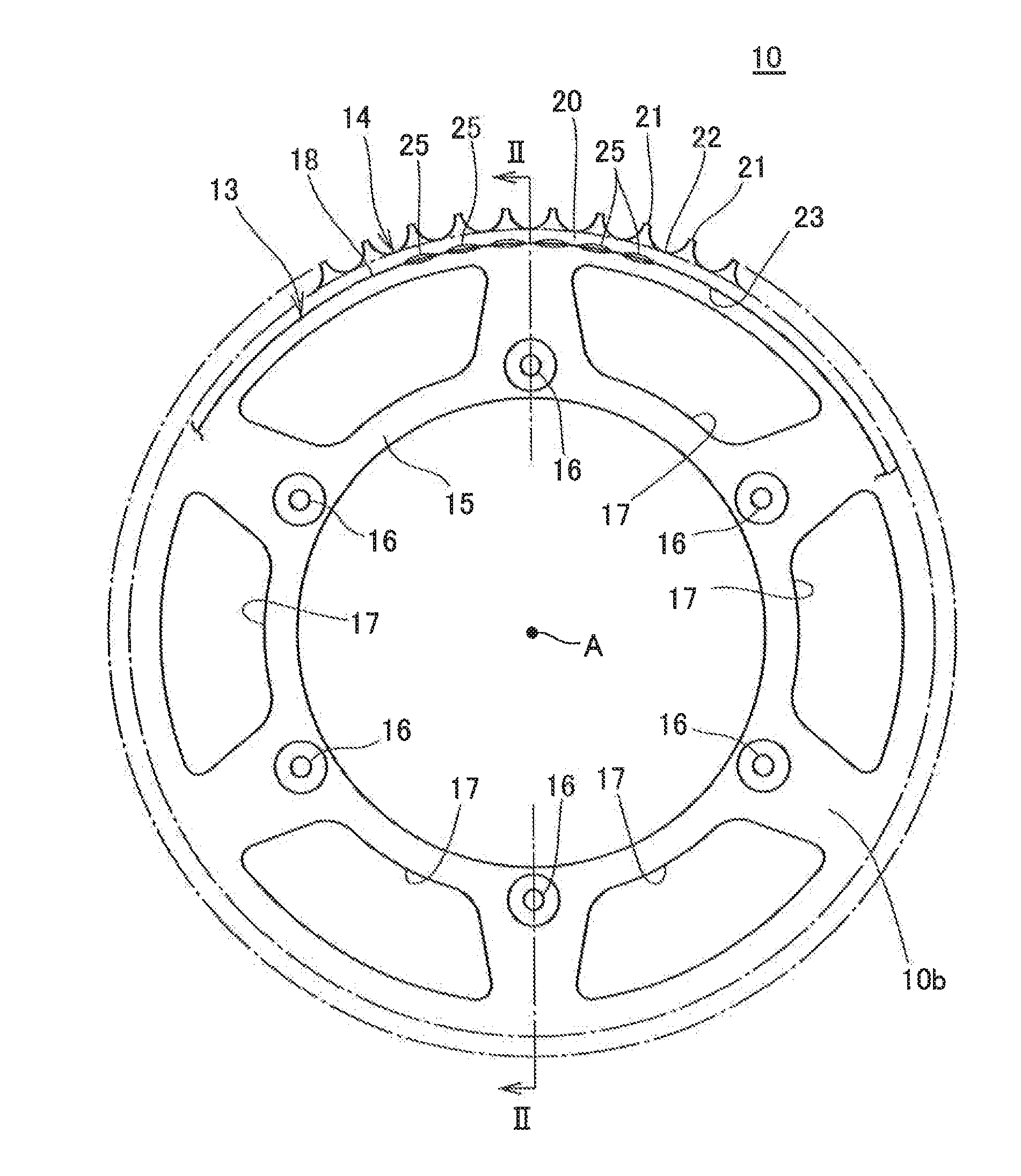
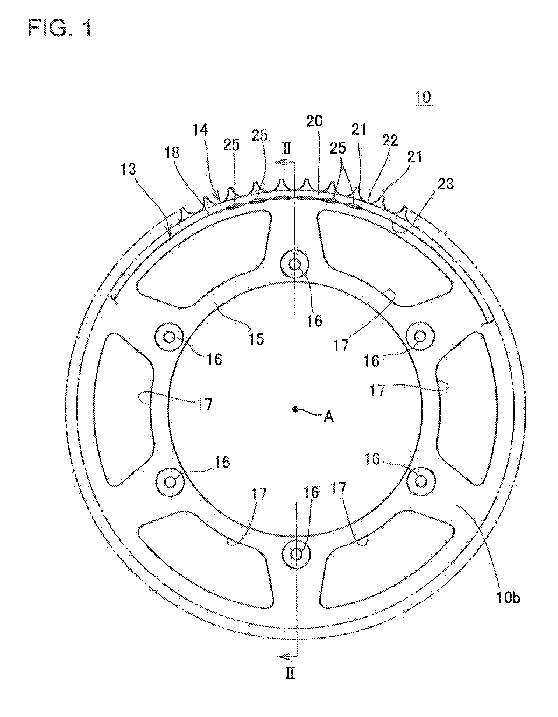
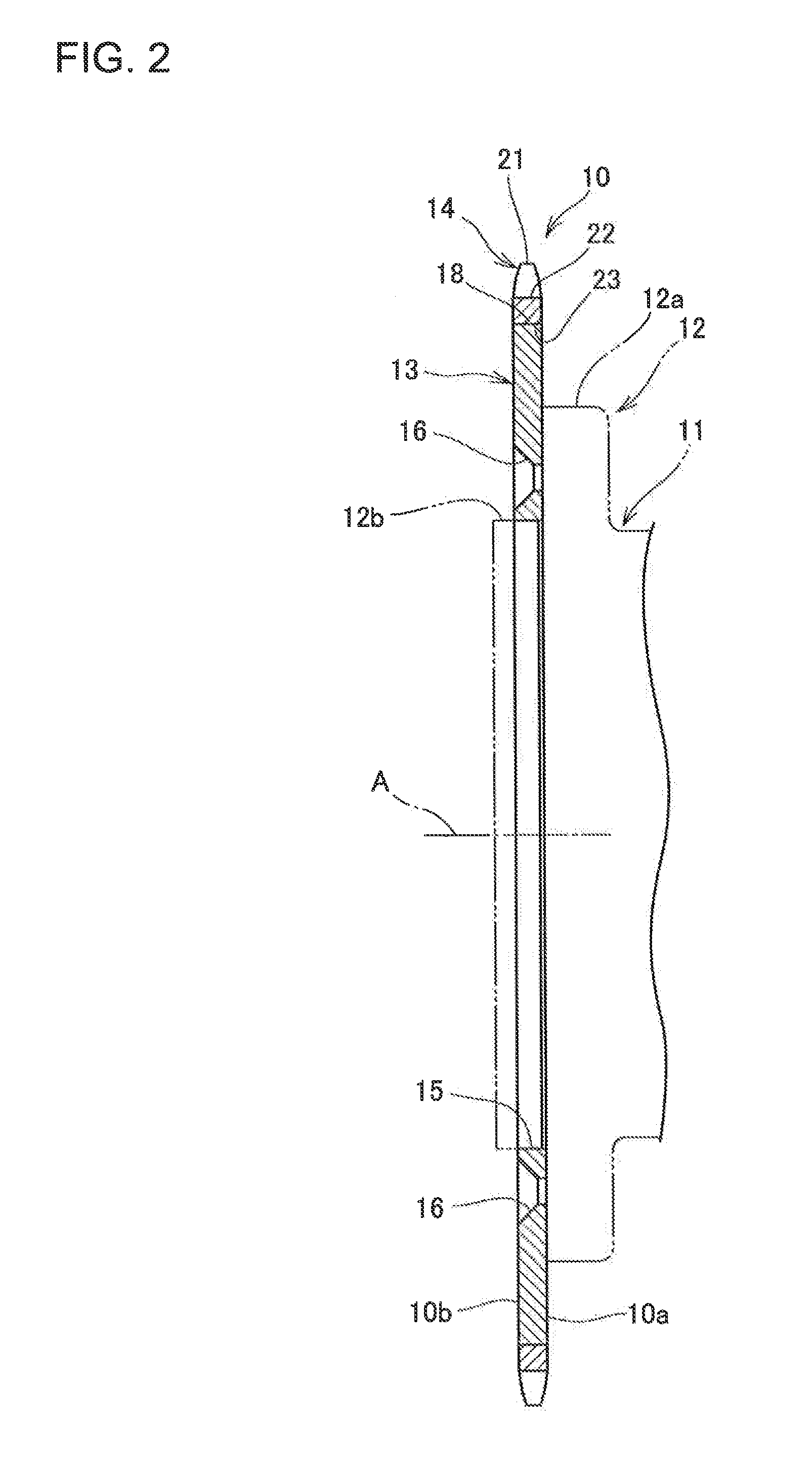
[0037]FIG. 1 is a front plan view of a sprocket assembly according to a first embodiment of the present invention. FIG. 2 is a cross-sectional view of the sprocket assembly of FIG. 1, taken along the line II-II. The sprocket assembly 10 may also be referred to herein as a sprocket 10.

[0038]The sprocket 10 may be used as a driven sprocket provided on a rear wheel of a vehicle, such as a driving wheel of a motorcycle (not shown). The motorcycle has a driving sprocket (not shown) provided on an engine output shaft, the sprocket 10, and an endless loop driving chain (not shown) put between the driving sprocket and the sprocket 10. Engine torque output is transmitted to the sprocket 10 via the driving sprocket and the driving chain, and the rear wheel is rotated integrally with the sprocket 10. The driving chain is a roller chain which may be formed of a ferrous material such as carbon steel.

[0039]As indicated with an alternate long and two short dashes line in FIG. 2, the wheel of the r...

second embodiment

[0063]A second embodiment to which the present invention is applied will be described below with reference to FIGS. 5 to 7. In the second embodiment, elements formed as in the case of the above-described first embodiment have the same reference numerals, and the explanations thereof will be omitted.

[0064]In the above-described first embodiment, the toothed ring member 14 has the annular member 20 having the teeth 21 integrally formed thereon. In contrast, in the second embodiment, the difference from the above-described first embodiment is that respective tooth members 114 are individually formed as separate bodies.

[0065]FIG. 5 is a partially expanded detail plan view of a part of the sprocket assembly in accordance with a second embodiment of the present invention.

[0066]The sprocket 110 has a circular disk 113 having a plurality of recessed notches 140 formed therein, and the plurality of tooth members 114 are connected to the outer periphery of the circular disk 113 at the respect...

third embodiment

[0085]A third embodiment to which the present invention is applied will be described below with reference to FIG. 8. In the third embodiment, elements formed as in the case of the above-described first embodiment have the same reference numerals, and the explanations thereof will be omitted.

[0086]In the above-described first embodiment, the toothed ring member 14 has the annular member 20 and the outer ring containing multiple teeth 21. In the second embodiment, the difference from the first embodiment is that the respective tooth members 114 are formed as separate bodies. Further, in the third embodiment, the difference from the first embodiment is that the welded part between a tooth member 214 and the circular disk 213 is formed to have a distance in the radial direction.

[0087]FIG. 8 is a plane diagram of an enlarged part of a sprocket 210 in the third embodiment.

[0088]The sprocket 210 has a circular disk 213 and a plurality of tooth members 214 connected to the outer periphery o...


PUM

PropertyMeasurementUnit
distanceaaaaaaaaaa
diametersaaaaaaaaaa
weightaaaaaaaaaa

Abstract

A sprocket assembly, formed of dissimilar materials, includes at least one tooth member made of ferrous material and a circular disk made of a light metal such as aluminum or an aluminum alloy. The circular disk supports the tooth member on an outer peripheral surface thereof. The tooth member is dissimilar-metal welded to the circular disk, either by laser welding or by electronic beam welding. Optionally, multiple individual tooth members may be fitted into notches formed in an outer periphery of the circular disk, and welded therein. A method of making a sprocket assembly is also described.

Description

CROSS-REFERENCE TO RELATED APPLICATIONS[0001]The present invention claims priority under 35 USC 119 based on Japanese patent application No. 2014-013141, filed on Jan. 28, 2014. The entire subject matter of this priority document, including specification claims and drawings, is incorporated by reference herein.BACKGROUND OF THE INVENTION[0002]1. Technical Field of the Invention[0003]The present invention relates to a sprocket. More particularly, the present invention relates to a sprocket formed from dissimilar materials, including a tooth member formed of ferrous material, and a circular disk, which is formed of a light metal and which supports the tooth member thereon.[0004]2. Background Art[0005]Conventionally, in a sprocket, a technique of connecting a circular disk with a tooth member by shrinkage fitting of a steel annular member having the tooth member on its periphery on the outer periphery of a circular disk of a light alloy such as aluminum, is known (for example, see Japa...

Claims


Application Information

Patent Timeline
Patent Type & Authority Applications(United States)
IPC IPC(8): F16H55/30B23K26/20B23K15/00
CPCF16H55/30B23K26/20B23K15/0046B23K15/04B23K26/28B23K2101/008B23K2103/18B23K2103/20B23K2103/24
Inventor INUI, SHUJIRO
Owner HONDA MOTOR CO LTD
Why Eureka
Try Eureka