
Distribution measurement system for pressure, temperature, strain of material, monitoring method for carbon dioxide geological sequestration, assessing method for impact of carbon dioxide injection on integrity of strata, and monitoring method for freezing using same

a technology of material strain and distribution measurement system, which is applied in the direction of heat measurement, force measurement by measuring optical property variation, instruments, etc., can solve the problem that the strain measured by this system is of no us

Active Publication Date: 2015-07-30
RES INST OF INNOVATIVE TECH FOR THE EARTH +1
View PDF7 Cites 26 Cited by
  • Summary
  • Abstract
  • Description
  • Claims
  • Application Information

AI Technical Summary

Benefits of technology

The invention provides a system that can accurately measure and simultaneously track changes in pressure, temperature, and strain on materials. This allows for the effective monitoring and evaluation of the state of vast materials underground.

Problems solved by technology

Since this system aims to measure distributions of pressure and temperature and the optical fiber is not fixed to an object to be measured, strain measured by this system is of no use.

Method used


Image

  • Distribution measurement system for pressure, temperature, strain of material, monitoring method for carbon dioxide geological sequestration, assessing method for impact of carbon dioxide injection on integrity of strata, and monitoring method for freezing using same
  • Distribution measurement system for pressure, temperature, strain of material, monitoring method for carbon dioxide geological sequestration, assessing method for impact of carbon dioxide injection on integrity of strata, and monitoring method for freezing using same
  • Distribution measurement system for pressure, temperature, strain of material, monitoring method for carbon dioxide geological sequestration, assessing method for impact of carbon dioxide injection on integrity of strata, and monitoring method for freezing using same

Examples


embodiment 1

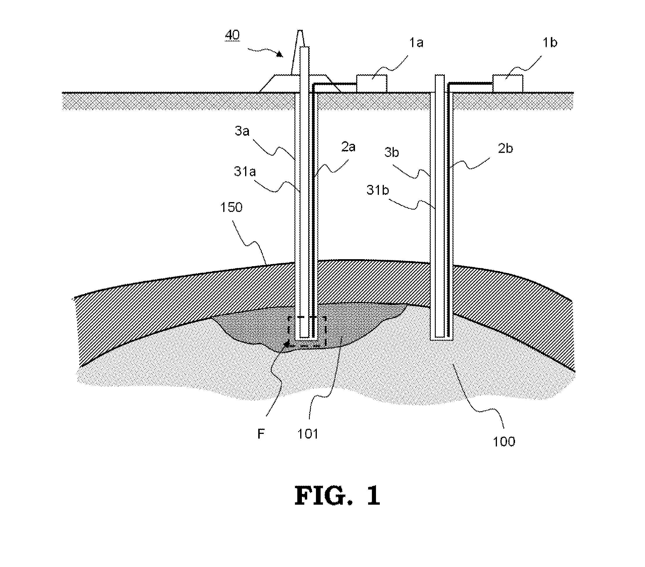
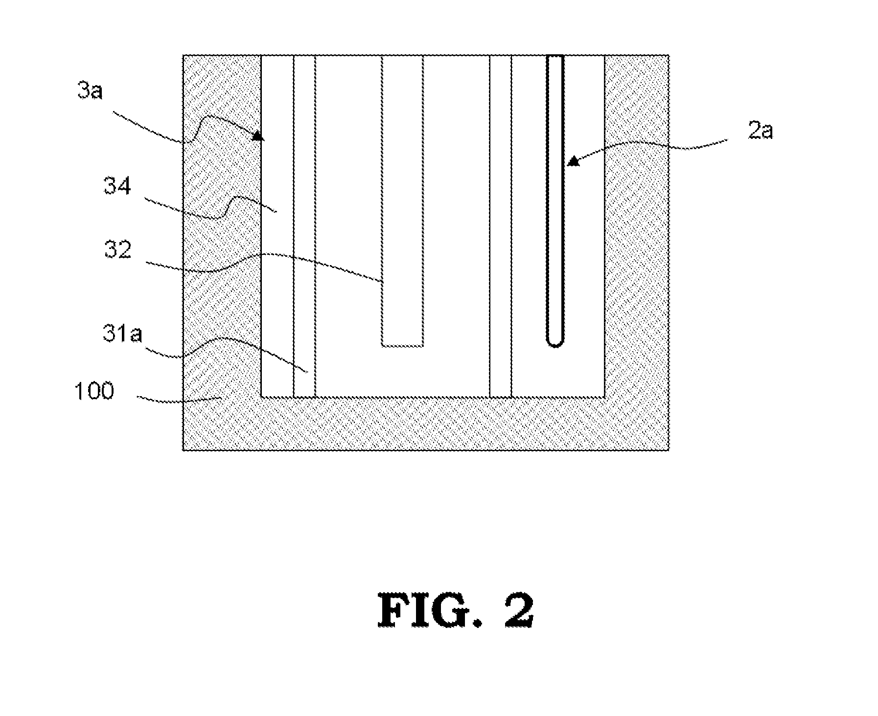
[0028]FIG. 1 is a schematic cross sectional view illustrating a system for monitoring carbon dioxide geological sequestration by mean of a system of Embodiment 1 of the present invention for measuring distributions of pressure, temperature, and strain of material; FIG. 2 is an enlarged view of the portion F in FIG. 1; and FIG. 3 is an enlarged cross sectional view of a sensor cable in FIG. 1. It is assumed that there exist under the ground a sandstone stratum 100 that is a carbon dioxide trapping stratum and a cap rock stratum 150 thereabove that serves as a seal stratum. A injection well 3a is drilled toward the underground sandstone stratum 100 from a storage site 40 set up on the ground. A cylindrical casing 31a having a carbon dioxide injection tube 32 inserted thereinside is installed in the injection well 3a. The casing 31a is fixed to underground strata by performing cementing 34 therearound. Near around the injection well 3a, an observation well 3b is often drilled to observ...

embodiment 2

[0052]Embodiment 2 describes an example of a laboratory experiment demonstrating that characteristics of extensive material such as geological strata can be monitored and measured by the system of the present invention for measuring distributions of pressure, temperature, and strain of material. FIG. 8 is a schematic diagram illustrating a configuration of the laboratory experiment. The configuration is such that an optical fiber 200 is spirally wounded around a cylindrical sample called Tago sandstone 110 having a bias in its porosity (permeability) to measure a Brillouin frequency shift and a Rayleigh frequency shift by DPTSS 1. As shown in FIG. 8, the Tago sandstone 110 consists of an upper portion with small porosity (fine layer) and a lower portion with large porosity (coarse layer) for simulating the cap rock stratum 150 and the sandstone 100 shown in FIG. 1, respectively.

[0053]After the sample was placed in a pressure vessel and then applied with a confining pressure of 12 MP...

embodiment 3

[0057]Embodiment 3 describes application examples enabled by the system of the present invention for measuring distributions of pressure, temperature, and strain of material.


PUM

PropertyMeasurementUnit
lengthaaaaaaaaaa
pressureaaaaaaaaaa
temperatureaaaaaaaaaa

Abstract

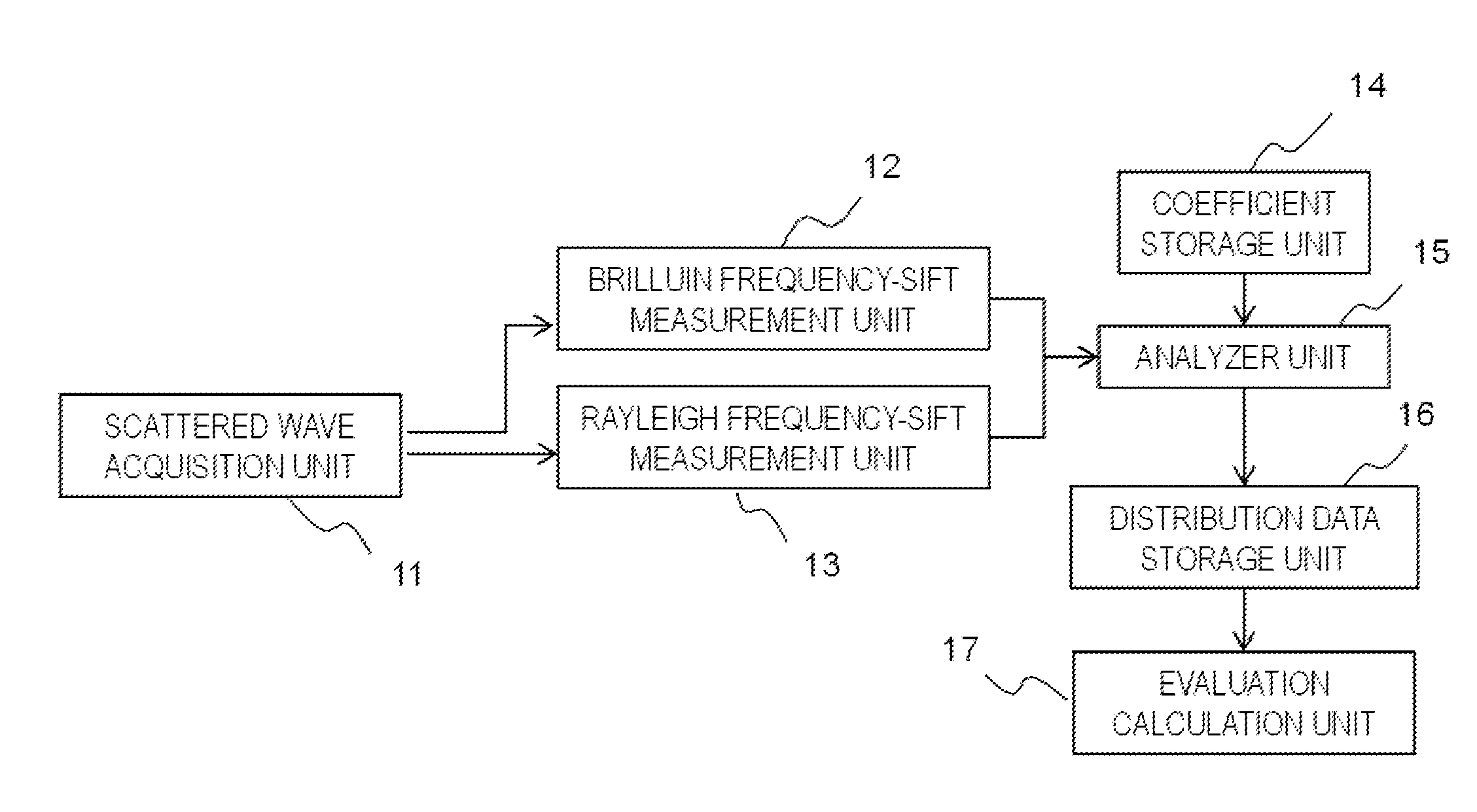
Distributions of a Brillouin frequency shift and a Rayleigh frequency shift in optical fibers set up in a material are measured from scattered waves of pulse laser light entered into the optical fibers, and distributions of pressure, temperature, and strain of the material along the optical fibers at a measurement time point are analyzed using coefficients that are inherent to the set up optical fibers and correlate pressure, temperature, and strain of material with the Brillouin frequency shift and the Rayleigh frequency shift.

Description

TECHNICAL FIELD[0001]The present invention relates to a system for measuring simultaneously distributions of pressure, temperature, and strain of material by mean of Brillouin frequency shift and Rayleigh frequency shift phenomena in an optical fiber, and further relates to a method of monitoring and measuring characteristics of extensive material such as geological strata using the system.BACKGROUND ART[0002]There are known various measuring techniques that use the Brillouin scattering phenomenon in an optical fiber (for example, Patent Document 1). One of the techniques is a distributed pressure sensor that utilizes a Brillouin frequency shift caused by strain applied to an optical fiber. Because the Brillouin frequency shift depends on strain applied to the optical fiber, pressure applied can be measured by analyzing the frequency shift of the optical fiber that is fixed to a material deformable by pressure.[0003]The present inventors have already proposed a system for measuring ...

Claims


Application Information

Patent Timeline
Patent Type & Authority Applications(United States)
IPC IPC(8): G01D5/353G01B11/16G01L1/24G01L19/00G01K11/32
CPCG01D5/353G01L19/00G01K2011/322G01L1/242G01B11/16G01K11/32G01B11/18G01D5/35361G01K11/322B01J19/00G01K11/12
Inventor XUE, ZIQIUYAMAUCHI, YOSHIAKIKISHIDA, KINZO
Owner RES INST OF INNOVATIVE TECH FOR THE EARTH
Learn More