System and method of detecting ultra weak magnetic field

a magnetic field and ultra-weak technology, applied in the field of system and method of detecting ultra-weak magnetic field, can solve the problems of inability to optimize signal detection, inability to manually regulate output voltage, and inability to detect very weak magnetic field in magnetic detection circuit for detecting magnetic field. achieve the effect of accurately detecting a very weak magnetic field and high sensitiveness

Active Publication Date: 2015-07-30
PROLIFIC TECH INC
View PDF13 Cites 7 Cited by
  • Summary
  • Abstract
  • Description
  • Claims
  • Application Information

AI Technical Summary

Benefits of technology

[0005]The exemplary embodiments of the disclosure may provide a magnetic field detection technique for detecting the intensity of the external magnetic field by using a magnetic impedance element whose impedance changes according to an external magnetic field. More particularly, the present invention relates to a magnetic field detection technique for highly sensitively and accurately detecting a very weak magnetic field generated by the terrestrial magnetism or a very weak electric current.

Problems solved by technology

Under such circumstances, it is difficult to manually regulate the output voltage.
It is also unable to optimize signal detection if magnetic field is not smooth or magnetic field changes dramatically, even coupled with nonlinear effect.
Therefore the magnetic detection circuit for detecting magnetic field is unable to detect very weak magnetic field especially for sub mG (milliGauss) magnetic field or detect noisy magnetic field.
As a result this detection technique will cause large error in modern application especially for application such as air mouse, gyro, etc.
The existing technologies of detecting magnetic field have drawbacks of unable to handle conditions such as element intrinsic noise of oscillation circuit, sampling jitter induced noise of peak voltage variation, coil loading effect that affecting non-external magnetic field characterization, weak magnetic field, etc.

Method used


Image

  • System and method of detecting ultra weak magnetic field
  • System and method of detecting ultra weak magnetic field
  • System and method of detecting ultra weak magnetic field

Examples


Embodiment Construction

[0019]Below, exemplary embodiments will be described in detail with reference to accompanying drawings so as to be easily realized by a person having ordinary knowledge in the art. The inventive concept may be embodied in various forms without being limited to the exemplary embodiments set forth herein. Descriptions of well-known parts are omitted for clarity, and like reference numerals refer to like elements throughout.

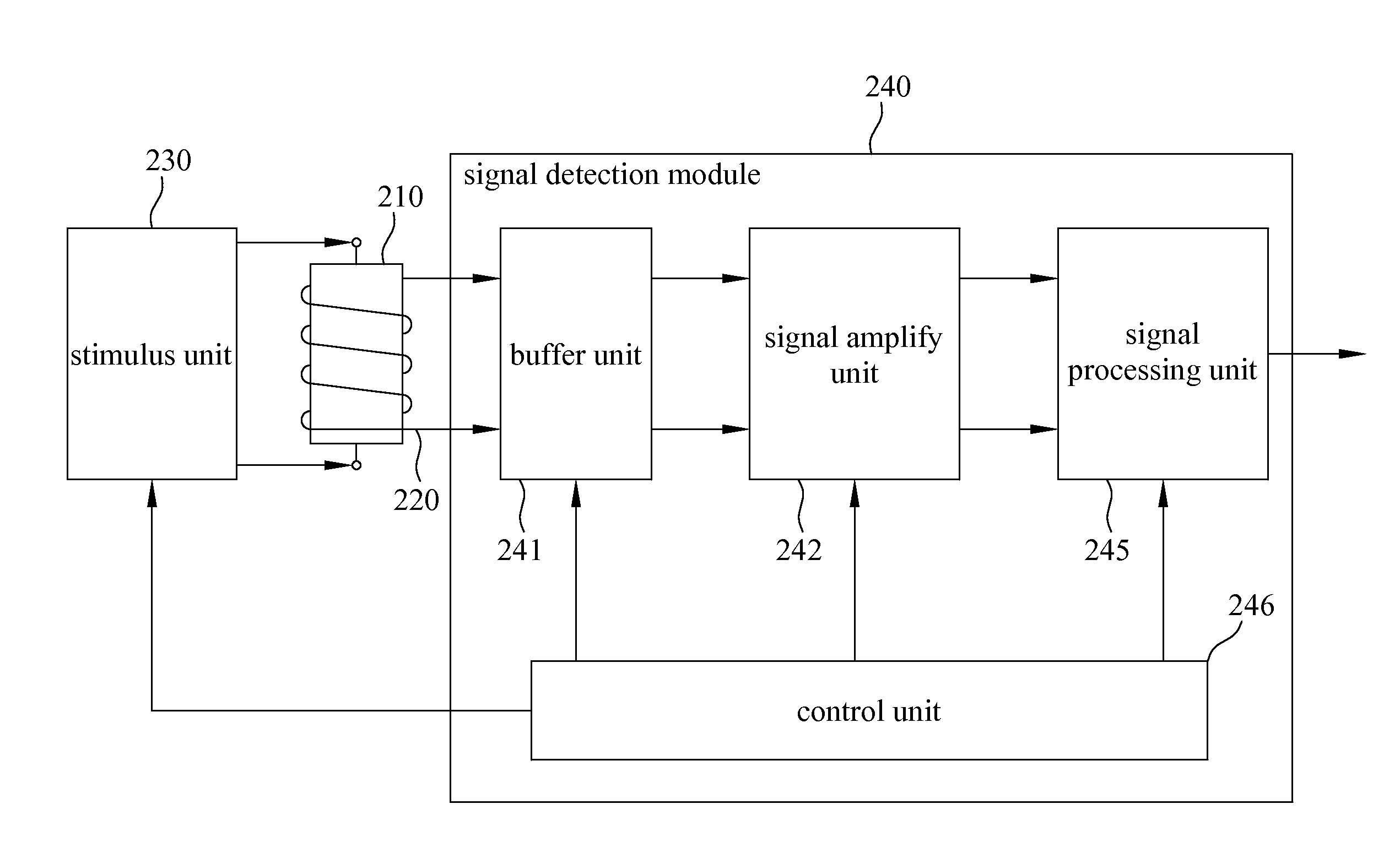
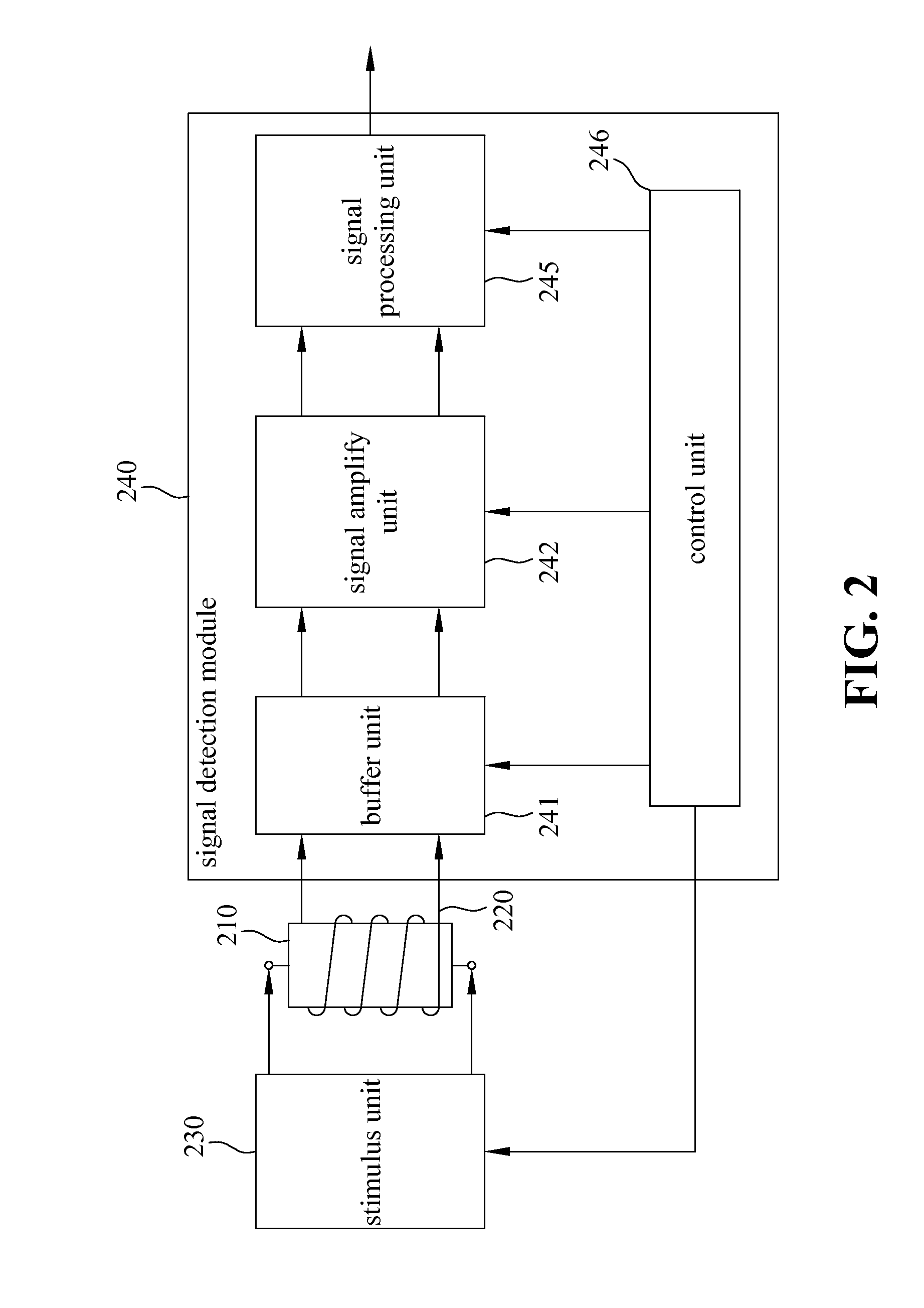
[0020]The exemplary embodiments in the disclosure provide a magnetic field detection technique for detecting the intensity of the external magnetic field by using a magnetic impedance element whose impedance changes according to an external magnetic field. More particularly, the present invention relates to a magnetic field detection technique for highly sensitively and accurately detecting a very weak magnetic field generated by the terrestrial magnetism or a very weak electric current.

[0021]One exemplary embodiment relates to a system of detecting magnetic field. ...


PUM


Abstract

According to one exemplary embodiment, a system of detecting magnetic field comprises a magnetic impedance element surrounded by a detection coil, a stimulus unit generates pulse signal of programmable rise / fall time to drive the magnetic impedance element, and a signal detection module detects signal on the detection coil, wherein the signal detection module includes a buffer unit having adjustable bandwidth shapes output signal of the detection coil, a signal amplify unit includes a sample and hold circuit and a chopping programmable gain amplifier to amplify buffered signal from the buffer unit, a signal processing unit processes amplified signal from the signal amplify unit by applying selectable algorithm to output detection result, and a control unit connects the signal processing unit to generate control parameters of the stimulus unit, the buffer unit, the signal amplify unit, and the signal processing unit.

Description

BACKGROUND[0001]Recently, technique adapted to detect the terrestrial magnetism has come to be required to highly sensitively and accurately detect a very weak magnetic field so as to broaden the scope of application. Magnetic impedance (MI) elements have been attracting attention as magnetic field detecting elements of this type. With a known magnetic field detecting method using MI element, the magnetic field is detected by directly applying a high frequency electric current to a magnetic element and detecting the voltage signal generated by the detection coil wound around or arranged in the vicinity of the magnetic element.[0002]FIG. 1 illustrates a basic circuit diagram of a circuit that can be used for detecting magnetic field. Referring to FIG. 1, a pulse oscillation is generated by means of an oscillation circuit 11 surrounded by broken lines and an electric current is made to flow to MI element 14 by way of inverter 12 and current regulating resistor 13. Then, the change in ...

Claims


Application Information

Patent Timeline
Patent Type & Authority Applications(United States)
IPC IPC(8): G01R33/00
CPCG01R33/0017G01R33/04G01R33/063G01R33/18
Inventor LU, CHIH-SHIUN
Owner PROLIFIC TECH INC
Why Eureka
Try Eureka