Supercharge Your Innovation With Domain-Expert AI Agents!

Negative resistance generator, load including negative resistance and load of amplifier

a technology of negative resistance and generator, applied in the direction of network simulating negative resistance, dc level change, pulse automatic control, etc., can solve the problems of increasing cost, increasing cost, and actual inductance not being ideal, and achieve the effect of improving the linearity of the amplifier

Active Publication Date: 2015-07-30
REALTEK SEMICON CORP
View PDF2 Cites 0 Cited by
  • Summary
  • Abstract
  • Description
  • Claims
  • Application Information

AI Technical Summary

Benefits of technology

The present patent describes a negative resistance generator that improves the linearity of transistors and a load that utilizes the generator. The negative resistance generator includes a first transistor and a second transistor connected between a power source circuit and a DC level setting circuit. The DC level setting circuit provides a second gate voltage to the second transistor based on the first AC component and the first DC component, and a first gate voltage to the first transistor based on the second AC component and the second DC component. The load includes a resonant circuit and a negative resistance generator connected between a power source circuit and a DC level setting circuit. The load uses the negative resistance generator to improve linearity, resulting in improved performance of the amplifier.

Problems solved by technology

However, as it is shown in FIG. 1a, an actual inductor is non-ideal and usually composed of an inductance L and a parasitic resistance Rs connected in series.
However, in consideration of that the Q value is positively proportional to the size of an inductor in an integrated circuit while an inductor of greater size consumes more circuit area and lead to the increase of cost, the Q value has to be determined with a dilemma of sacrificing performance or cost benefit.
1), which also leads to the increase of cost.
As a result, a designer again faces the dilemma of sacrificing performance or cost benefit again.
Unfortunately, the active region of transistor(s) under this kind of technique is inclined to enter the linear region from the saturation region due to a larger AC (Alternating Current) signal swing, which causes the linearity to be worse and therefore required to be improved as well.

Method used


Image

  • Negative resistance generator, load including negative resistance and load of amplifier
  • Negative resistance generator, load including negative resistance and load of amplifier
  • Negative resistance generator, load including negative resistance and load of amplifier

Examples


Embodiment Construction

[0019]The following description is written by referring to terms of this technical field. If any term is defined in this specification, such term should be explained accordingly. In addition, the connection between objects or events in the below-described embodiments can be direct or indirect provided that these embodiments are practicable under such connection. Said “indirect” means that an intermediate object or a physical space exists between the objects, or an intermediate event or a time interval exists between the events.

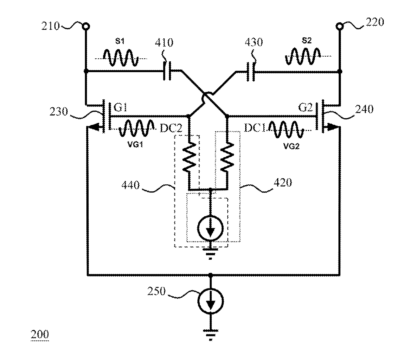
[0020]The present disclosure discloses a negative resistance generator, a load including negative resistance and a load of an amplifier, and the negative resistance generator, the load including negative resistance and the load of the amplifier are capable of reducing a chance of the active region of transistor(s) entering the triode region from the saturation region for linearity improvement. Each of the devices is applicable to an integrated circuit (e.g., a...


PUM


Abstract

A negative resistance generator is disclosed herein. The negative resistance generator includes a first signal end for receiving a first signal which includes first AC / DC components, a second signal end for receiving a second signal which includes second AC / DC components, first and second transistors, a power source circuit, a first and a second DC level setting circuits. The power source circuit is coupled to the first and second transistors. The first DC level setting circuit provides a second gate voltage for a second gate of the second transistor according to a first DC voltage and the first AC component. The second DC level setting circuit provides a first gate voltage for a first gate of the first transistor according to a second DC voltage and the second AC component. The second gate voltage and first gate voltage are lower than the voltages of the first and the second signal respectively.

Description

BACKGROUND OF THE INVENTION[0001]1. Field of the Invention[0002]The present disclosure relates to a resistance generator and a load, especially to a negative resistance generator and a load including negative resistance.[0003]2. Description of Related Art[0004]An ideal inductor in comparison with a resistor has the feature of lossless DC (Direct Current) transmission. Therefore, in some circuit design, an inductor instead of a resistor is used as a load for the linearity improvement of circuit operation. For instance, when developing a low noise amplifier (LNA), an inductor could be used for impedance match and treated as a load such that the linearity of this amplifier would improve. However, as it is shown in FIG. 1a, an actual inductor is non-ideal and usually composed of an inductance L and a parasitic resistance Rs connected in series. If the inductance L and the resistance Rs in FIG. 1a are represented by a substitution of the inductance L and a resistance Rp connected in para...

Claims


Application Information

Patent Timeline
Patent Type & Authority Applications(United States)
IPC IPC(8): H03K5/003
CPCH03K5/003H03H11/52
Inventor SU, HSUAN-YI
Owner REALTEK SEMICON CORP
Features
  • R&D
  • Intellectual Property
  • Life Sciences
  • Materials
  • Tech Scout
  • Unparalleled Data Quality
  • Higher Quality Content
  • 60% Fewer Hallucinations
Learn More