
Internal combustion engine control device and method

a control device and internal combustion engine technology, applied in the direction of electric control, machines/engines, output power, etc., can solve the problems of likely knocking or the like, reduce the compression pressure of air, reduce the possibility of knocking, and achieve satisfactory fuel economy.

Inactive Publication Date: 2015-08-06
HITACHI AUTOMOTIVE SYST LTD
View PDF14 Cites 17 Cited by
  • Summary
  • Abstract
  • Description
  • Claims
  • Application Information

AI Technical Summary

Benefits of technology

The patent is about a system that reduces knocking in an engine and improves fuel economy. This is achieved by reducing the pressure of air before it reaches the engine during deceleration. This also allows for a variable compression ratio mechanism to be used, which increases fuel economy without sacrificing performance. Another benefit is that a reduction in intake air amount can also be achieved without negatively impacting performance.

Problems solved by technology

Therefore, a highly compressed intake air and an excessive intake air amount are reached so that knocking or the like is likely to occur.

Method used


Image

  • Internal combustion engine control device and method
  • Internal combustion engine control device and method
  • Internal combustion engine control device and method

Examples


first embodiment

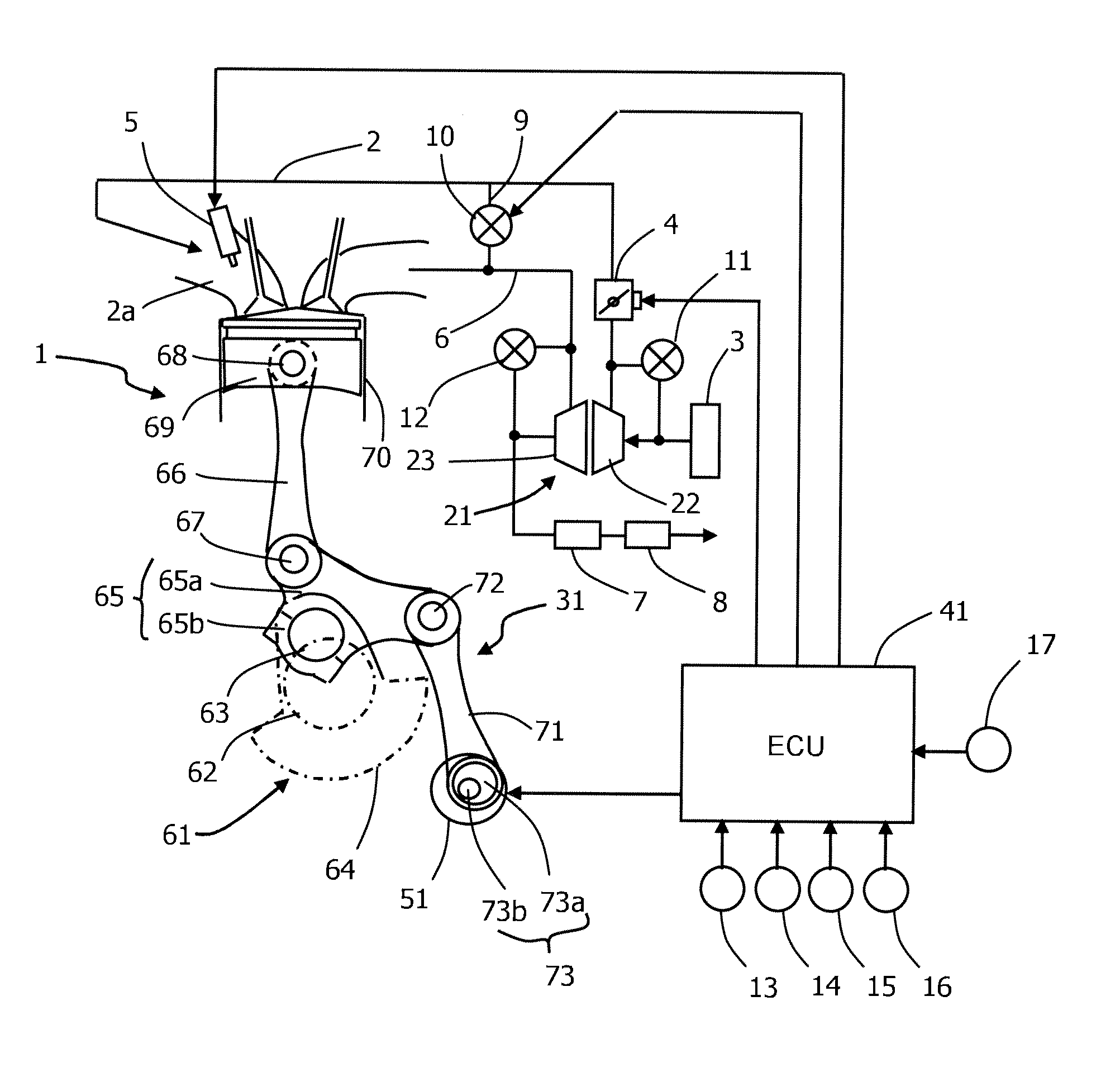
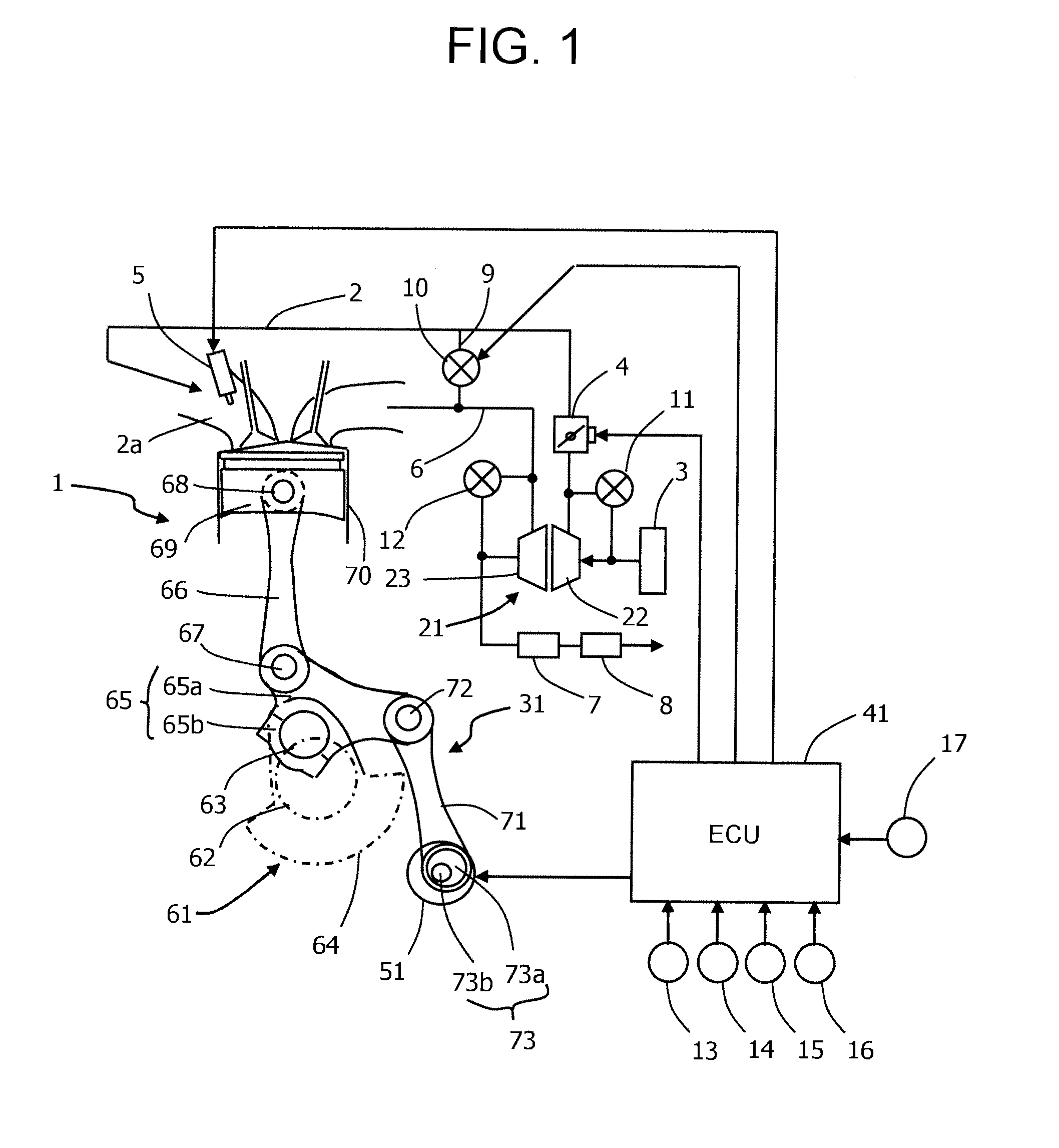
[0019]FIG. 1 illustrates an overview of an engine system according to a

[0020]An air cleaner 3, a compressor 22 of an exhaust turbo supercharger 21, and an electrically controlled throttle valve 4 for adjusting an intake air amount are interposed in an intake passage 2 of an engine 1 (internal combustion engine) from the upstream side, and a fuel injection valve 5 is attached to an intake port 2a portion.

[0021]A turbine 23 of exhaust turbo supercharger 21, an exhaust gas purifying catalyst 7 for purifying an exhaust, and a muffler 8 are interposed in an exhaust passage 6 from the upstream side.

[0022]An EGR passage 9 that connects exhaust passage 6 between engine 1 and exhaust gas purifying catalyst 7, to intake passage 2 downstream of throttle valve 4, is disposed. An EGR control valve 10 for adjusting an EGR amount is interposed in EGR passage 9.

[0023]An air bypass valve 11 opened under a predetermined condition is interposed in a passage, which bypasses compressor 22, of intake pas...

second embodiment

[0060]A description will hereinafter be made about a second embodiment that performs inertial supercharging and is applied to an engine equipped with a variable compression ratio mechanism.

[0061]FIG. 4 illustrates an overview of an engine system according to the second embodiment. The description of components common to the first embodiment will be omitted.

[0062]An engine 100 includes an inertial supercharging mechanism 110 provided in an intake passage 101.

[0063]A passage leading from an air cleaner 102 via a throttle valve 103 and an intake collector 104 to an intake port 105 serves as intake passage 101. Inertial supercharging mechanism 110 is provided at a portion leading from intake collector 104 to intake port 105.

[0064]Inertial supercharging mechanism 110 includes a first passage 111 that has a long passage length and a second passage 112 that has a short passage length. First passage 111 and second passage 112 are connected to each other in parallel at a downstream portion o...


PUM


Abstract

In an internal combustion engine equipped with a variable compression ratio mechanism, the occurrence of knocking is reduced during deceleration. When it is determined that a target compression ratio of the variable compression ratio mechanism is greater than a threshold PRSL during the deceleration, an air bypass valve interposed in a passage for bypassing a compressor of an exhaust turbo supercharger is opened to return intake air upstream (between the compressor and a throttle valve) of the throttle valve to upstream of the compressor, thereby reducing intake pressure upstream of the throttle valve and reducing in-cylinder compression pressure to reduce the occurrence of knocking.

Description

TECHNICAL FIELD[0001]The present invention relates to a control device and to a method for an internal combustion engine equipped with a variable compression ratio mechanism.BACKGROUND ART[0002]A variable compression ratio mechanism for varying a compression ratio has been developed to improve fuel economy of internal combustion engines. In an internal combustion engine equipped with the variable compression ratio mechanism, a usage form is common which avoids knocking or pre-ignition (knocking or the like) by setting a low compression ratio in a high load range and achieves an improvement in fuel economy by setting a high compression ratio in a low load range.[0003]Here, when deceleration operation to make a transition from a high load state to a low load state is performed, a response delay of a compression ratio change by the variable compression ratio mechanism is less than a response delay of a decrease in intake air amount. Therefore, a highly compressed intake air and an exce...

Claims


Application Information

Patent Timeline
Patent Type & Authority Applications(United States)
IPC IPC(8): F02D41/00F02D13/02F02D23/02F01L13/08
CPCY02T10/146Y02T10/144F02B27/0242F02B27/0273F02D15/02F02D41/0007F01L13/08F02D13/0234F02D23/02F02D41/0005F02D23/00F02B27/0215F02B37/16F02M26/05Y02T10/12Y02T10/40
Inventor KURASHIMA, YOSHIKUNI
Owner HITACHI AUTOMOTIVE SYST LTD
Learn More