
Pressure jet propulsion system

a technology of pressure jet and propulsion system, which is applied in the direction of mechanical equipment, machines/engines, transportation and packaging, etc., can solve the problems of high cost, high cost, and high cost of components, and achieve the effects of increasing cooling efficiency, dissipating heat generation, and increasing the surface area dissipation of hea

Inactive Publication Date: 2015-08-13
PROENTERPRIZ
View PDF8 Cites 7 Cited by
  • Summary
  • Abstract
  • Description
  • Claims
  • Application Information

AI Technical Summary

Benefits of technology

The patent text describes a pressure jet propulsion system for a helicopter that includes an air compressor and a mast mount assembly. The air compressor generates a mass flow of compressed air that can be directed to the blades of a helicopter to provide power. The system also includes a swashplate assembly that can adjust the pitch of the blades to control the movement of the helicopter. The system provides improved cooling efficiency and can be used in cold weather conditions. Overall, the system provides a more powerful and efficient way to propel helicopters.

Problems solved by technology

Pressure jet propulsion technology back in the 1940's and 1950's did not reach the appeal of manufacturers due to the limited development of engine and compressor technologies and the undesirable weight of the components at the time.
This change in pitch requires power changes which again cause counter-torque.
Conventional helicopters also have a complex mechanical assembly of components that interconnect the main rotor with the tail rotor.
These components are not only relatively heavy, but they require frequent and costly maintenance.

Method used


Image

  • Pressure jet propulsion system
  • Pressure jet propulsion system
  • Pressure jet propulsion system

Examples


Embodiment Construction

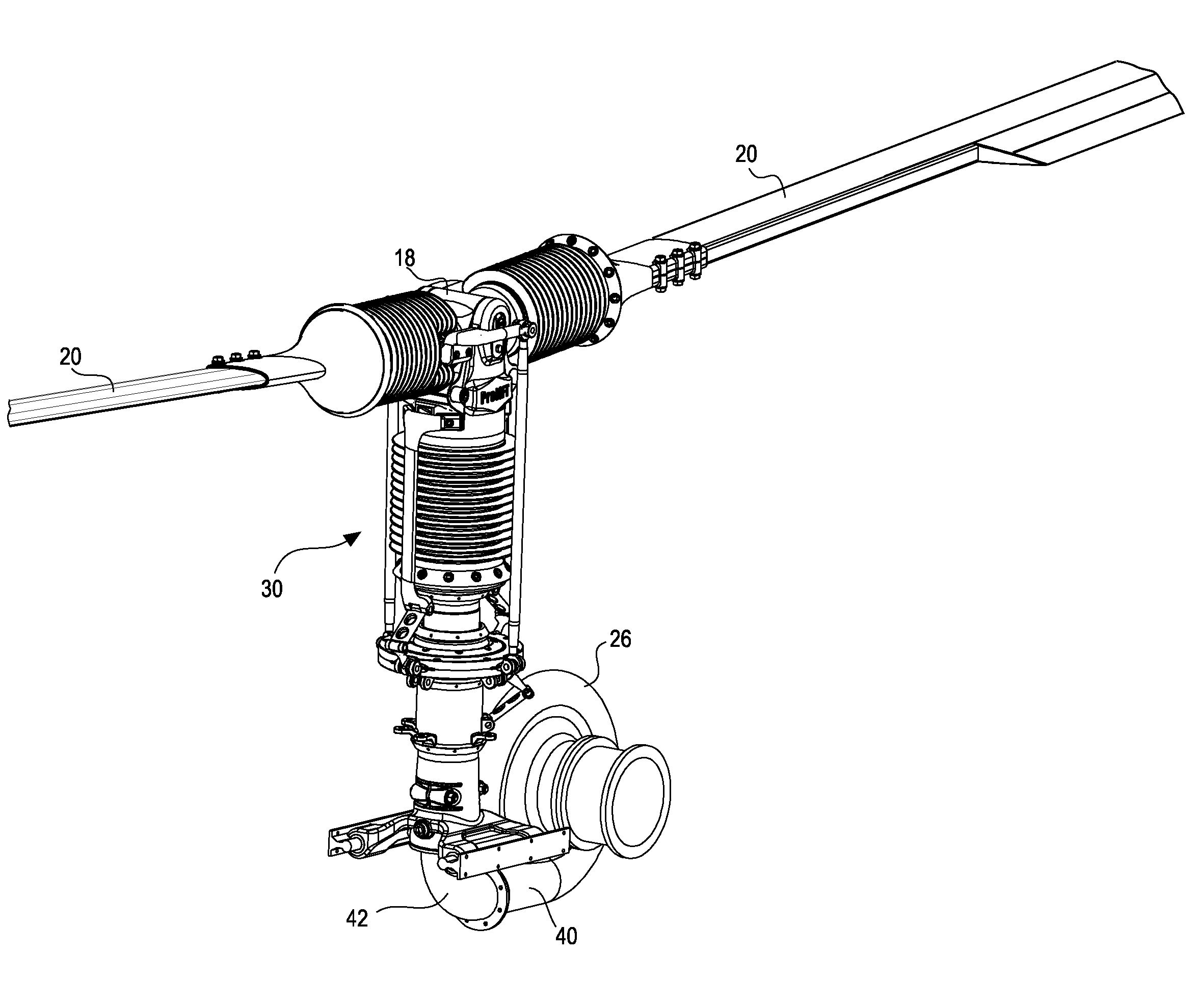
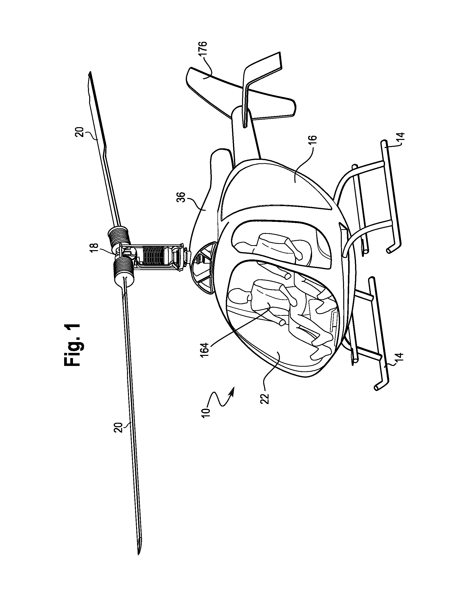
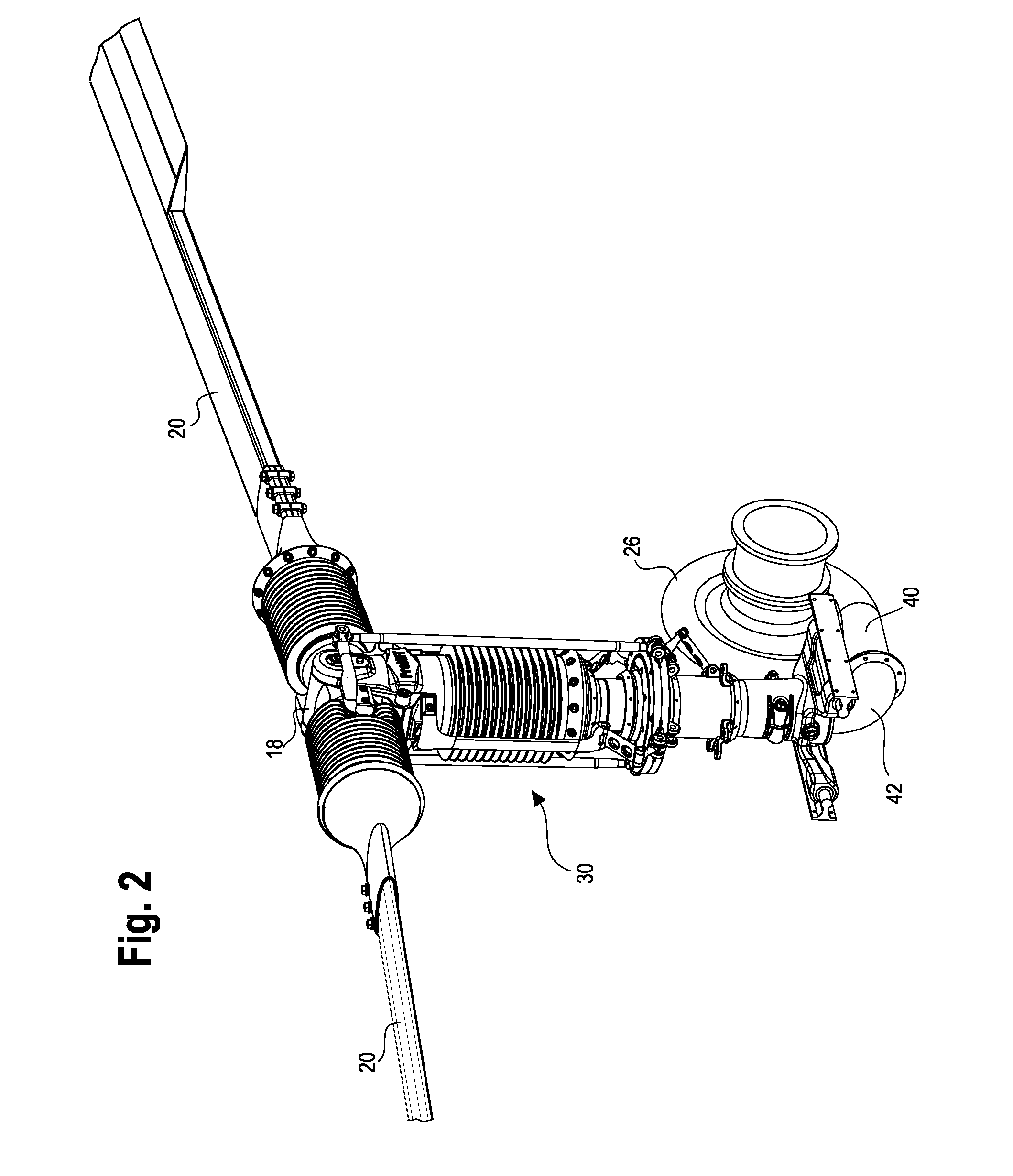
[0052]As shown in the drawings for purposes of illustration, the present invention for a pressure jet propulsion system is generally shown with respect to the embodiments in FIGS. 1-32. More specifically, the pressure jet propulsion system disclosed herein is shown generally as integrated into a helicopter 10 as shown in FIGS. 1 and 3-6. Although, persons of ordinary skill in the art will readily recognize that the pressure jet propulsion system may be incorporated into existing helicopter designs as a retrofit system and / or optional propulsion system, such as the helicopter 10′ shown in FIG. 35. The helicopter 10 can be as simple as the design shown in FIGS. 1 and 3-6, including a tubular frame 12 and skids 14, a molded fuselage 16, a cast Titanium rotor hub 18, at least a pair of fabricated blades 20, a simple wiring loop with readily available instruments, a Plexiglas windshield 22 and doors 24, a reciprocating piston engine or turbine engine, a centrifugal compressor 26 and rela...


PUM


Abstract

The pressure jet propulsion disclosed herein generally includes an air compressor for generating a mass flow of compressed air and a mast mount assembly in fluid communication with the air compressor for receiving and channeling the mass flow of compressed air. A positioning system supports the mast mount assembly and is movable on-demand to relocate the mast mount assembly relative to a center of gravity in response to environmental changes. Furthermore, at least two blades are in fluid communication with the mass flow of compressed air from the movable mast mount assembly, which is discharged through an outlet at an angle relative to an axis of rotation to cause rotation of the blades.

Description

BACKGROUND OF THE INVENTION[0001]The present invention generally relates to a pressure jet propulsion system for a helicopter or the like. More specifically, the present invention relates to a pressure jet propulsion system for a helicopter that includes rotor blades driven by compressed air that travels up a mast, into the rotor head, down the length of each blade and exits at the tip of the blade causing the rotor blades to rotate.[0002]Conventional helicopter technology started in about the 1940's. At that time, two main technologies were being developed, one that included a rogue version of the pressure jet propulsion technology as has been improved upon herein, and the more conventional and well known designs that were developed around a piston driven engine and turbine engine with direct drive technology. Pressure jet propulsion technology back in the 1940's and 1950's did not reach the appeal of manufacturers due to the limited development of engine and compressor technologie...

Claims


Application Information

Patent Timeline
IPC IPC(8): B64C27/12B64C27/06F01D25/12F01D5/28
CPCB64C27/12F01D25/12B64C27/06F01D5/28B64C27/18B64C27/32B64C27/605
Inventor LAWRENCE, PHILLIP G.
Owner PROENTERPRIZ
Learn More