Tethered wing system for wind energy use

a technology of wind energy and wing system, which is applied in the direction of machines/engines, transportation and packaging, toys, etc., can solve the problems of high air resistance, inefficient aerodynamic wing, and limited size and growth potential of this design, and achieve optimal energy generation and excellent gliding and flying characteristics

Active Publication Date: 2015-08-13
ENERKITE
View PDF33 Cites 14 Cited by
  • Summary
  • Abstract
  • Description
  • Claims
  • Application Information

AI Technical Summary

Benefits of technology

[0017]The invention-related design is however characterized by the fact that it allows controlled and efficient flight movements of a single passive aerodynamic surface in two completely separated operating points, where here, the control is done via retaining and control tethers only from the ground. In this way and only this way, it is possible for the first time to forgo active control in the wing.
[0020]Surprisingly, it was found that through the selected design, the different rigid and elastic materials used, which can be joined together form-fitted and force-fitted according to the invention, as well as the use of a central bridle line (4), which conventional commercial systems do not have, excellent gliding and flying characteristics (aerodynamic resistance of cW <0.20, mainly <0.15; aerodynamic lift cA >1.0, mainly >1.5) with optimal energy generation (>2 mainly >5 kW / m2 wing area) can be achieved by the raising and lowering of the wing, in particular in the yoyo operation by the ground station.

Problems solved by technology

This is associated with a surface weight of 20-60 kg / m2 for small and 50-150 kg / m2 for large systems, so that the size and growth potential of this design is naturally limited.
The disadvantages of this system are: (a) The easy collapse of the wing when there is no inflow also at the start because there are no rigid elements; (b) the need for a finely branched tethering for the load transfer, which leads to high air resistance and thus an aerodynamically inefficient wing and (c) reduced or missing efficient retrieval operation.
A ram pressure wing with very low or negative angles of approach and accordingly low lift and drag coefficients cannot be flown due to the migratory ram pressure point, the special tethering and fluctuating inflow in turbulent air.
Disadvantages of tube kites are, for example: Constant pressurization of structural elements is expensive, relatively heavy and prone to defects in the technical implementation.
The design loses its rigidity in the event of possible leaks.
Active pressurization to compensate for leakage increases the weight, energy consumption and costs in an undesirable manner.
The famous sail-like designs also tend to flutter under certain inflow conditions which would affect the reliability and durability.
The drawbacks of known wing systems with rigid structure are as follows: The use of, e.g. a glider-like aircraft conies with high weights.
The wings are so heavy that they cannot be started at wind speeds in the operating area of the system without additional tools.
The costs for wings of this construction are relatively high due to the materials used and manufacturing expenses.

Method used


Image

  • Tethered wing system for wind energy use
  • Tethered wing system for wind energy use
  • Tethered wing system for wind energy use

Examples


Embodiment Construction

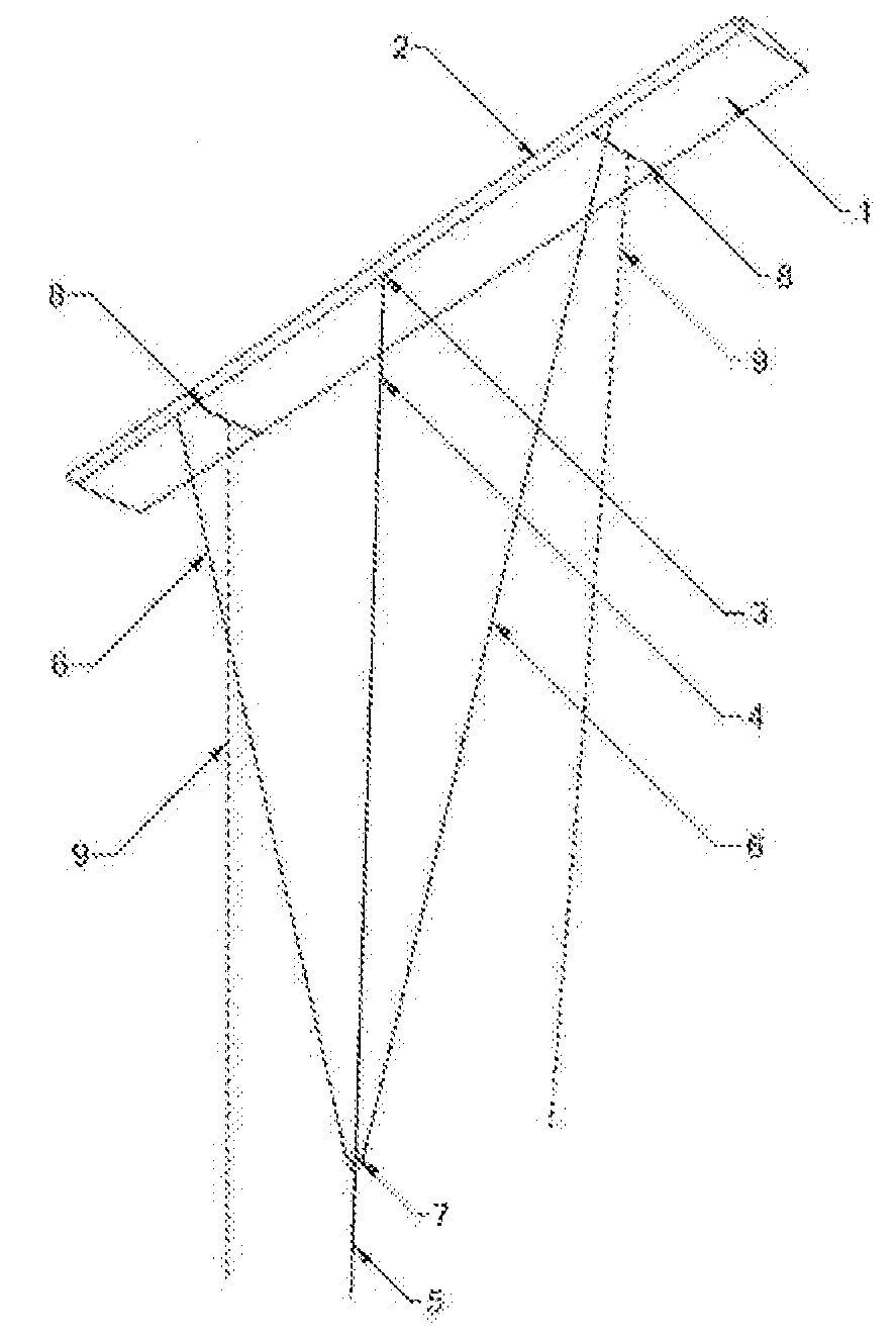
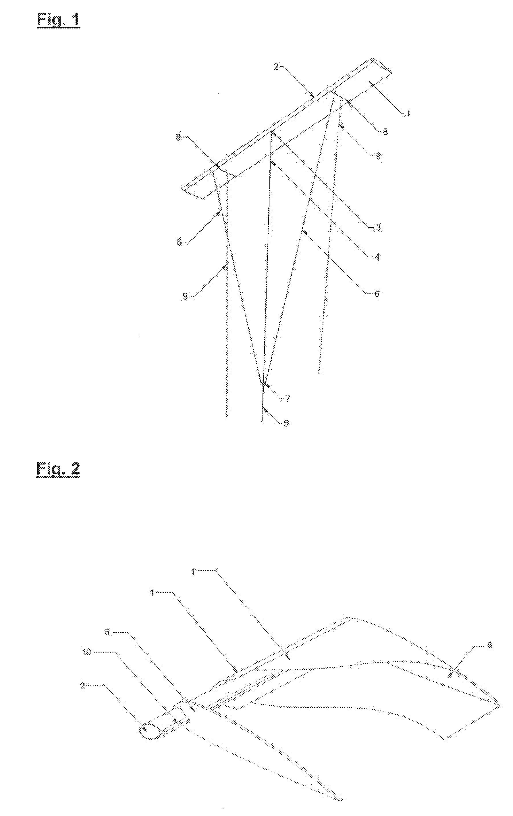
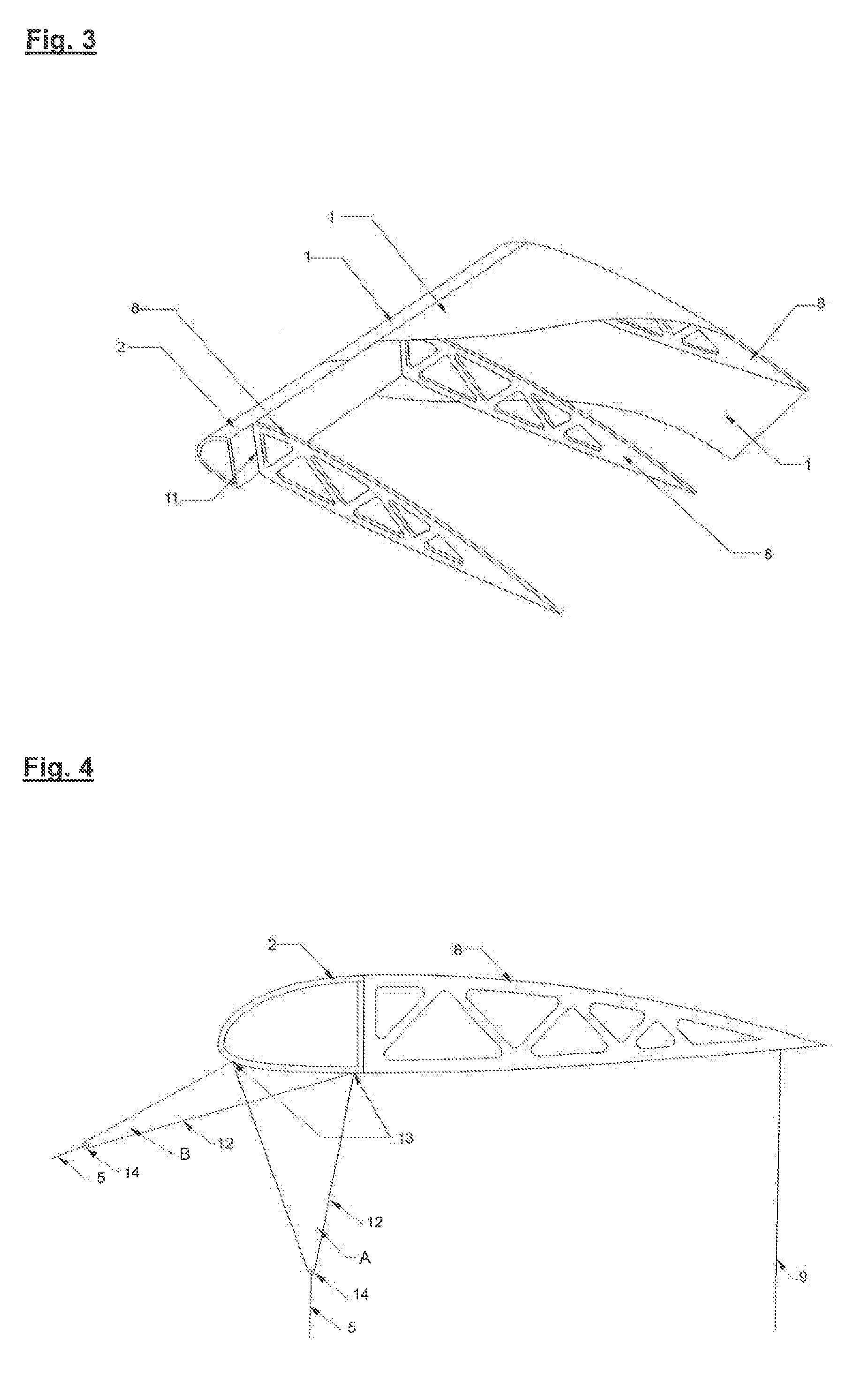
[0037]In a preferred embodiment, the invention-related wing design includes a multi-part wing bridle (5, 6, 7, 12, 13) consisting of tensile tethers, single, branched or multiply branched. Alternatively, the invention-related wing design has guidance devices (15, 16, 17) in the area of the profile spar (2), making it possible that the central bridle line (4) and / or the connection element (18, 19) and / or the wing bridles (5, 6, 7, 12, 13) can be moved backwards and forwards, so that the said elements can take a lateral or transverse position to the wing or also positions in between.

[0038]The profile spar (2) has a D-form (closed) according to the invention or an open U-shape and is made of a hard but flexible material, preferably of plastic. Typically, the connection devices (3, 4, 5, 6, 7, 18, 14) are attached in the area of the largest load impact, so preferably in the area of the profile spar (2). In doing so, said elements can be in the lower part of the spar profile body outside...


PUM


Abstract

A tethered passive wing system for the conversion of flow energy into electric energy which exhibits optimized aerodynamic and mechanical properties for reliable and efficient operation and is only connected through one or more tensile elements to a converter unit and comprises an optimized combination of rigid, non-flexural structural elements such as, for example, beams and shell structures and flexible fabric structures, such as, for example, membranes, films, laminates.

Description

FIELD OF THE INVENTION[0001]The invention refers to a tethered wing system and its production for a wind turbine e.g. for the conversion of flow energy into electric energy which exhibits optimized aerodynamic and mechanical properties for the reliable and efficient operation and is only connected through one or more tensile elements to a converter unit and consists of an optimized combination of rigid, non-flexural structural elements such as, for example, beams and shell structures and flexible fabric structures, such as, for example, membranes, films, laminates. The invention-related wings exhibit very advantageous physical properties such as wing load, surface weight and performance yield.BACKGROUND OF THE INVENTION, THE KNOWN PRIOR ART AND DISADVANTAGES[0002]Airborne wind turbines are not connected to high structures fixed to the ground such as towers and poles. The flow energy of the wind is converted by the tethered aircraft into mechanical and electrical energy. The advantag...

Claims


Application Information

Patent Timeline
Patent Type & Authority Applications(United States)
IPC IPC(8): B64C39/02F03D9/00F03D5/00B64C31/06B64F3/00
CPCB64C39/022B64C31/06F03D9/002F03D5/00B64F3/00F05B2240/921Y02E10/70F03D9/25Y02E10/72F03D9/32
Inventor BORMANN, ALEXANDERSKUTNIK, STEFANGEBHARDT, CHRISTIANRANNEBERG, MAXIMILIAN
Owner ENERKITE
Why Eureka
Try Eureka