Turbo-molecular pump

Active Publication Date: 2015-08-13
SHIMADZU CORP
View PDF0 Cites 18 Cited by
  • Summary
  • Abstract
  • Description
  • Claims
  • Application Information

AI Technical Summary

Benefits of technology

[0014]The present invention makes it possible to improve the exha

Problems solved by technology

However, when a larger amount of gas is discharged, the temperature of a rotor that includes the moving blades may disadvantageously exceed an allowable temperature.
As a result, the rotor may disadvantageously come into contact with a

Method used


Image

  • Turbo-molecular pump
  • Turbo-molecular pump
  • Turbo-molecular pump

Examples


Example

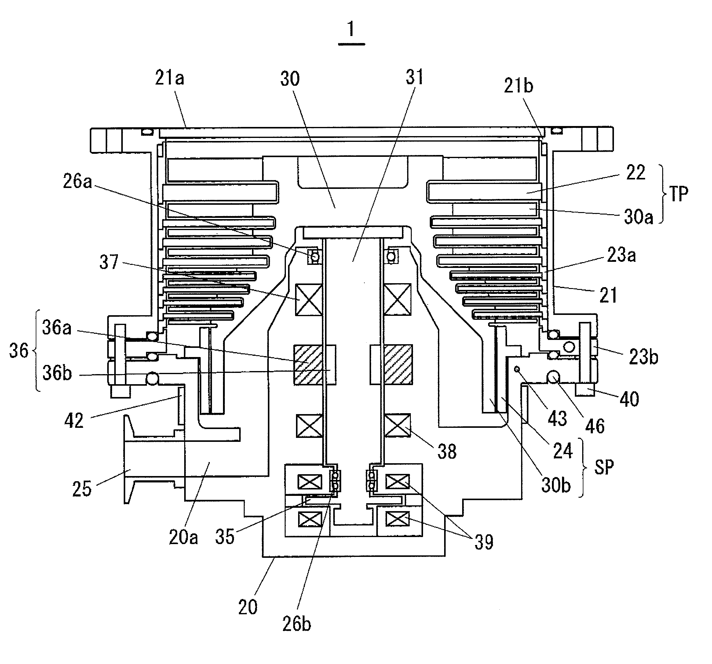
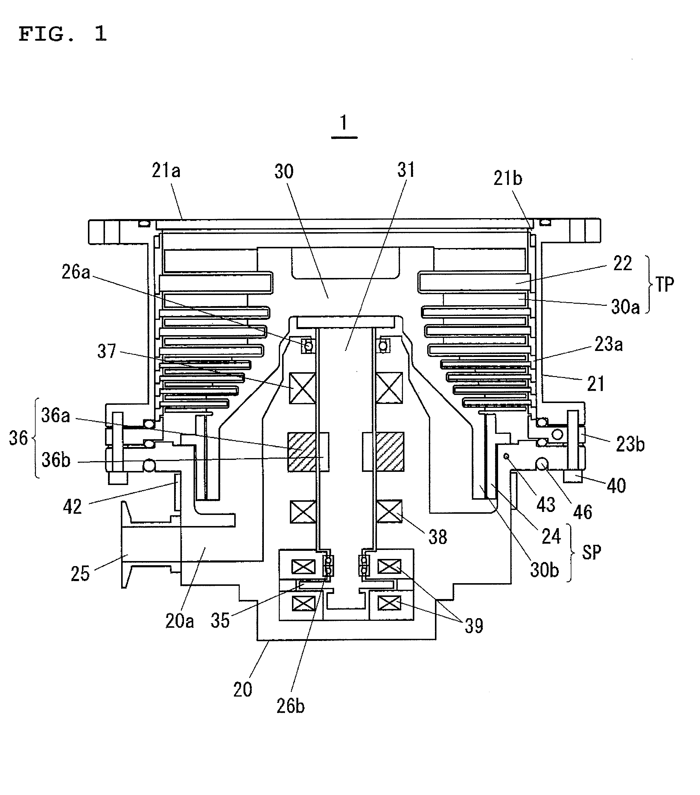
[0024]Hereinafter, an embodiment of the present invention will be described with reference to the drawings. FIG. 1 is a diagram showing a schematic configuration of a turbo-molecular pump according to the present invention. The turbo-molecular pump includes a pump main body 1 shown in FIG. 1 and a control unit (not shown) which controls the drive of the pump main body 1. The control unit is provided with a main controller which controls the entire pump main body, a motor controller which drives a motor 36 (described below), a bearing controller which controls magnetic bearings provided in the pump main body 1, a temperature regulation controller 511 (described below), or the like.

[0025]In the following description, an active magnetic bearing turbo-molecular pump will be described as an example. However, the present invention can also be applied, for example, to passive magnetic bearing turbo-molecular pumps using a permanent magnet or turbo-molecular pumps using a mechanical bearing...


PUM


Abstract

A turbo-molecular pump comprises: a rotor; stationary blades; a stator; a plurality of spacers; a heater disposed on the base; a temperature sensor for detecting a temperature of the stator; and a temperature regulation section for on/off controlling the heater based on a temperature detected by the temperature sensor to regulate the temperature of the stator so as to be a reaction product accumulation prevention temperature. At least one spacer arranged on a base side of the plurality of spacers is cooled by coolant, and the turbo-molecular pump further comprises a heat insulation member disposed between the base and the spacer arranged on the base.

Description

TECHNICAL FIELD[0001]The present invention relates to a turbo-molecular pump provided with a turbine blade section and a screw groove pump section.BACKGROUND ART[0002]Conventionally, in a dry etching process, a CVD process, or the like in semiconductor manufacturing processes, processing is performed while supplying a large amount of gas in order to perform the processes at high speed. Generally, a turbo-molecular pump that is provided with a turbine blade section and a screw groove pump section is used for evacuating a process chamber in a dry etching process, a CVD process, or the like. When a large amount of gas is discharged in a turbo-molecular pump, frictional heat generated in moving blades (rotor blades) is transmitted from the moving blades to stator blades (stationary blades), spacers, and a base in this order, and then released into cooling water in a cooling pipe disposed on the base.[0003]However, when a larger amount of gas is discharged, the temperature of a rotor tha...

Claims


Application Information

Patent Timeline
IPC IPC(8): F04D27/00F04D29/58F04D19/04
CPCF04D27/006F04D29/5853F04D29/582F04D19/042F04D29/584F04D19/044F05D2260/607
Inventor TSUTSUI, SHINGO
Owner SHIMADZU CORP
Why Eureka
Try Eureka