Bifurcated dual-balloon catheter system for bifurcated vessels

a dual-balloon, bifurcated technology, applied in the direction of dilators, sensors, domestic objects, etc., can solve the problems of unproven success, overlap of balloons on one side of the main branch, and the balloon delivery system that assists in positioning the stents with accuracy

Inactive Publication Date: 2015-08-20
AL SAADON KHALID
View PDF3 Cites 8 Cited by
  • Summary
  • Abstract
  • Description
  • Claims
  • Application Information

AI Technical Summary

Benefits of technology

[0012]The present invention solves the aforementioned and other disadvantages of the prior art by providing a dual-balloon bifurcated balloon catheter for use in

Problems solved by technology

Other previous balloon delivery systems that assist in positioning the stents with accuracy in the bifurcated lesions, particularly involved in the procedure of double balloon sequential dilation for the stent, have not proven to be very successful.
Their limitations have led to the development of specifically designed balloons to treat bifurcation lesions, such as in U.S. Pat. No. 6,017,324 to Tu et al.
This design has its limitations in that it will help to solve specific bifurcation lesions when the distal branches have a Y-shape and the size of the distal vessels are smaller than the size of the proximal vessel (e.g. the aortic artery at bifurcation with iliac arteries) but it is not suitable if the size of one of the distal branches is equal to the proximal vessel size, and not suitable for the side branched vessels which are the majority of the cases.
The difficulty in using two balloons at a T-shaped bifurcated vessel is that the balloons overlap in one side of the main branch.
When expanded, this causes the overlapping balloon portions to expand more than the distal portion of the balloon in the other side of the

Method used


Image

  • Bifurcated dual-balloon catheter system for bifurcated vessels
  • Bifurcated dual-balloon catheter system for bifurcated vessels
  • Bifurcated dual-balloon catheter system for bifurcated vessels

Examples


Embodiment Construction

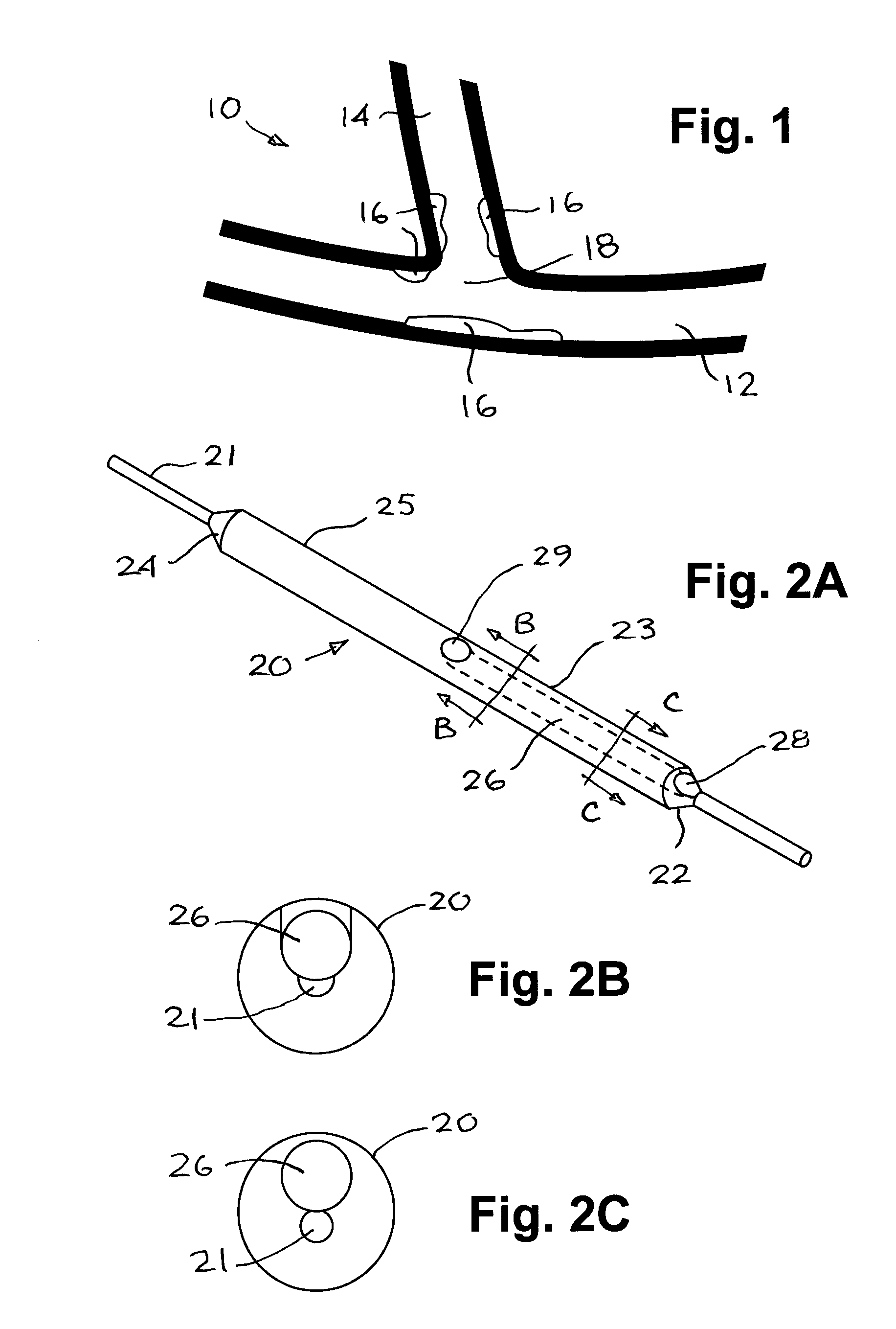
[0034]FIG. 1 shows a typical bifurcated vessel 10 of the T-type comprising a main vessel 12 and a side branch vessel 14 extending therefrom and having plaque or lesions 16 at or about the juncture 18 of the vessels 12, 14.

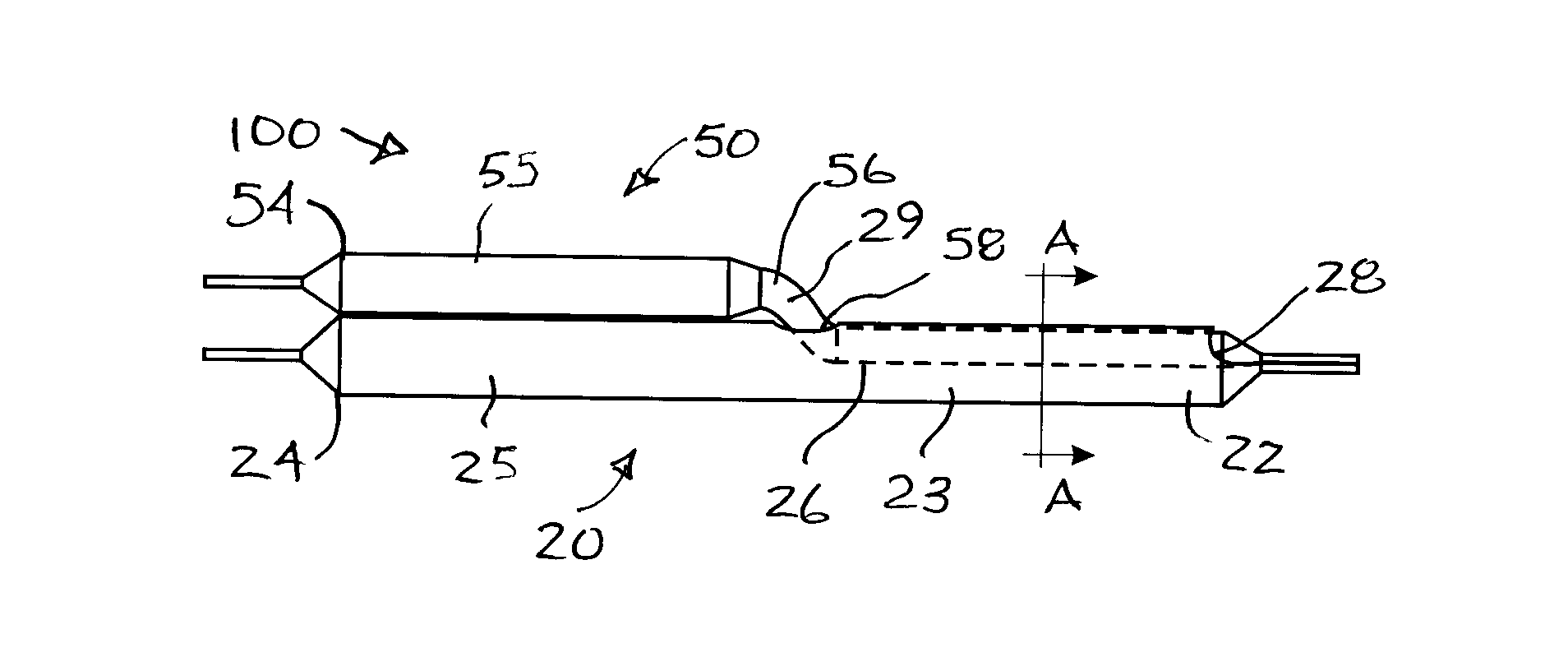
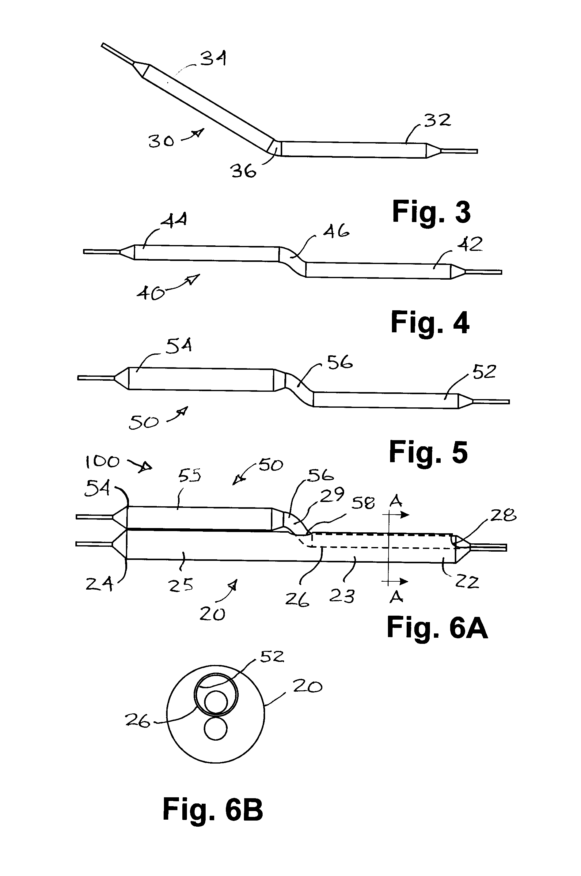
[0035]The preferred embodiment of the first or main branch balloon is illustrated at 20 in FIG. 2A in its expanded state. The main branch balloon 20 is disposed on a portion of a catheter 21 which extends through the main branch balloon 20. Catheter 21 is used to deploy the balloon 20 to the bifurcated vessel region through the use of guide wires (not shown in FIG. 2A) as well as to communicate inflation fluid to the balloon 20. The portion of the catheter 21 within the balloon 20 is not shown (with hidden lines) for sake of clarity. Similarly, the catheter 21 may contain one or more lumens, which are also not shown for sake of clarity. Main branch balloon 20 has a proximal end 22 and a distal end 24. When the terms proximal and distal are used herein, they normall...


PUM

PropertyMeasurementUnit
Angleaaaaaaaaaa
Angleaaaaaaaaaa
Shapeaaaaaaaaaa

Abstract

A bifurcated dual-balloon catheter apparatus for deploying one or more stents to a bifurcated vessel or for use in angioplasty procedures involving bifurcated vessels. The apparatus is particularly suited for bifurcated vessels of the type comprising a main branch from which a side branch extends therefrom. The apparatus has loon and a side branch balloon. A conduit is provided in the main branch balloon through which a portion of the side branch balloon extends. The first balloon is positionable within the main branch of the vessel while the distal portion of the second balloon is positionable within the side branch such that when the first and second balloons are inflated, the first balloon expands radially in the main branch while the distal portion of said second balloon maintains registration with the side branch by expanding radially therein.

Description

FIELD OF THE INVENTION[0001]The present invention relates to an inflatable balloon apparatus for deploying one or more stents to a bifurcated vessel or for use in angioplasty procedures involving bifurcated vessels. The apparatus is particularly suited for bifurcated vessels of the type comprising a main branch from which a side branch extends therefrom.BACKGROUND OF THE INVENTION[0002]The term stent has been used interchangeably with terms such as intraluminal vascular graft and expansible prosthesis. As used throughout this specification, the term stent is intended to have a broad meaning and encompasses any expandable prosthetic device for implantation in a body passageway (e.g. a lumen or artery).[0003]There have been various attempts at addressing the delivery and deployment of stents at bifurcated lesions. Bifurcated vessels may be of the Y-type, wherein a main branch bifurcates into two secondary branches, or of the T-type, wherein a side branch extends from a main branch. Wh...

Claims


Application Information

Patent Timeline
IPC IPC(8): A61F2/856A61F2/82A61F2/954A61F2/958A61M25/10A61M25/09
CPCA61F2/856A61M25/1011A61M25/09A61M25/104A61M2025/0183A61F2/954A61F2/958A61F2/82A61M2025/1045A61M25/1029B29L2031/7543B29C49/08
Inventor AL-SAADON, KHALID
Owner AL SAADON KHALID
Why Eureka
Try Eureka