Atmospheric measurement system

Active Publication Date: 2015-08-20
MICHIGAN AEROSPACE
View PDF0 Cites 43 Cited by
  • Summary
  • Abstract
  • Description
  • Claims
  • Application Information

AI Technical Summary

Benefits of technology

[0005]In at least one embodiment, the present invention relates to an apparatus that provides for simultaneous measurement of the wind upstream and downstream of a wind turbine using LIDAR, with the wind turbulence downstream of the turbine and its effect on other turbines of primary focus in this invention. A single LID

Problems solved by technology

The shorter wavelength ultraviolet light provides additional stealth characteristics for the system because the lig

Method used


Image

  • Atmospheric measurement system
  • Atmospheric measurement system
  • Atmospheric measurement system

Examples


Embodiment Construction

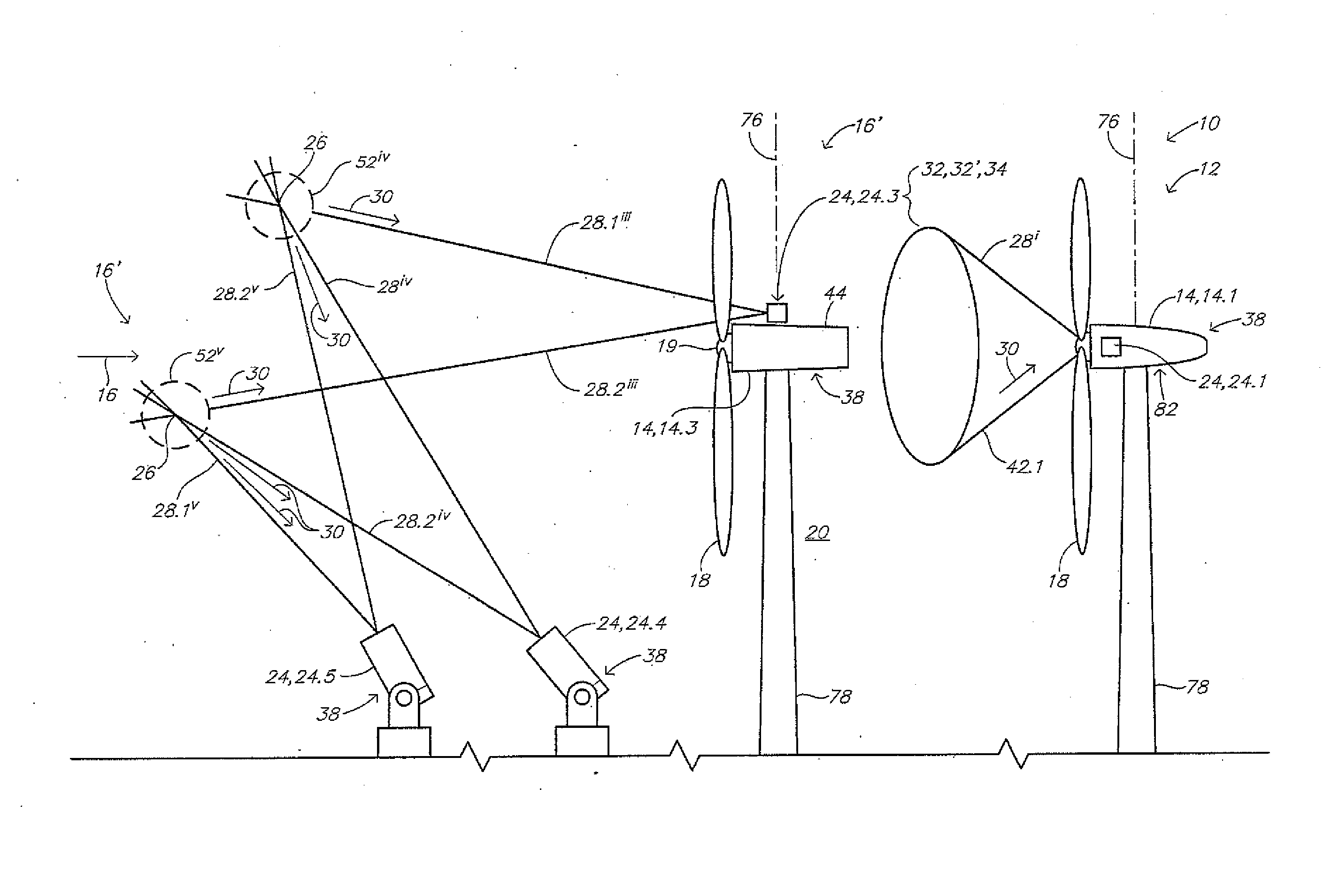
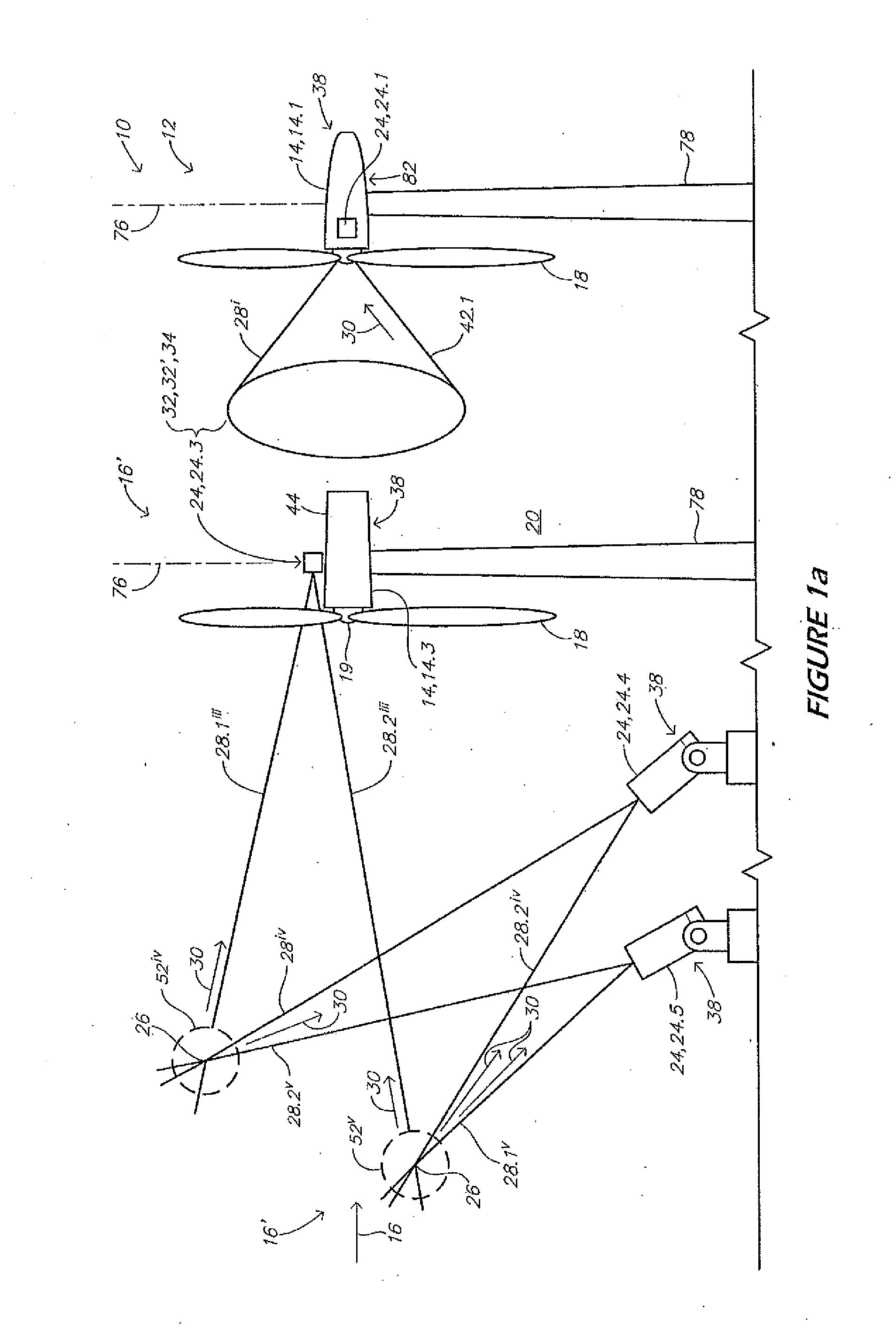
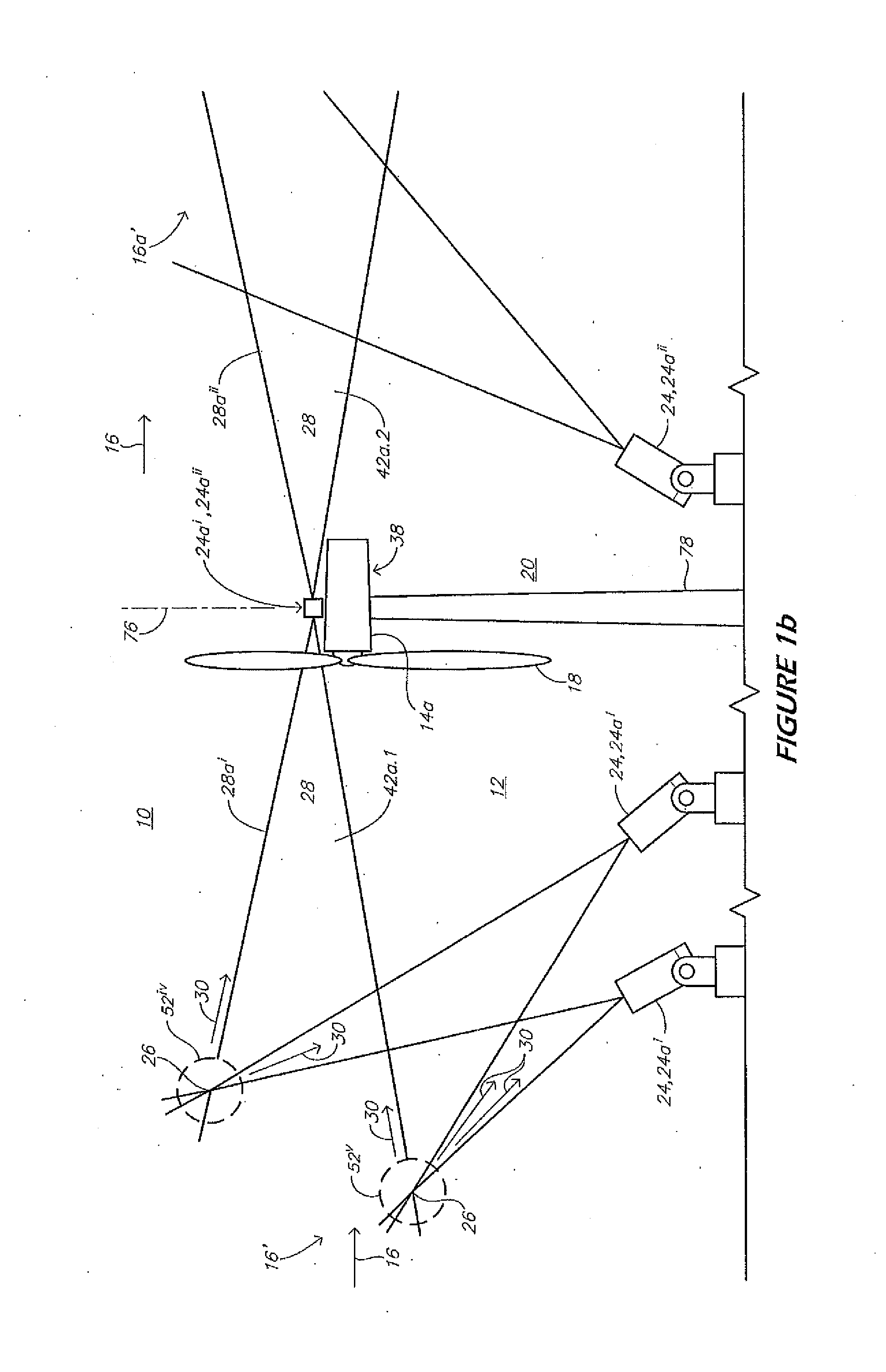
[0036]In a general embodiment of the present invention, with reference to FIGS. 1a and 2a, an atmospheric measurement system 10 is illustrated in association with a wind farm 12 comprising a plurality of wind turbines 14 that are used to generate power, e.g. electrical power, from the wind 16.

[0037]The atmospheric measurement system 10 provides for generating a measure of wind power flux density ψ over the geographic area of the wind farm 12, which can be used to predict an upper bound on power generating capability of each of the wind turbines 14 thereof, and which can accordingly be used for controlling the wind turbines 14 responsive thereto. More particularly, the atmospheric measurement system 10 comprises a network 22 of LIDAR sensors 24, each of which provide for remotely sensing atmospheric data including wind speed ν and atmospheric density ρ at one or more different range bins 26 along one or more associated beams of light 28 projected into the atmosphere 20, from scattere...


PUM


Abstract

An apparatus providing for simultaneous measurement of the wind upstream and downstream of a wind turbine uses either a single LIDAR beam split into two beams, each focused upstream or downstream of the windmill, or a multiple beam LIDAR with a first beam source aimed toward the upstream direction of the wind and a second beam source aimed at the downstream direction after the wind has passed through the wind turbine. The apparatus may also use LIDAR to measure wind direction and speed by making measurements along slightly different lines of sight, or by pointing the LIDAR in different directions. Two lines of sight allow measuring wind direction in the plane defined by the two lines of sight. Three non-coplanar lines of sight provide the information necessary to determine a full 3-dimensional wind velocity vector. Further, LIDAR may also be used to measure wind speed by estimating the wind velocity using inputs from both aerosol and molecular components.

Description

CROSS-REFERENCE TO RELATED APPLICATIONS[0001]This application claims the benefit of U.S. Provisional Application No. 61 / 732,210, filed on Nov. 30, 2012; and is the U.S. National Stage of PCT Application No. PCT / US2013 / 064693, filed Oct. 11, 2013, which is a continuation-in-part application of U.S. National Stage application Ser. No. 13 / 387,553, and claims priority thereto. U.S. National Stage application Ser. No. 13 / 387,553 claims priority from PCT / US2010 / 043801 filed Jul. 29, 2010, which claims the priority of U.S. Provisional Patent Application Ser. No. 61 / 229,608, filed on Jul. 29, 2009, U.S. Provisional Patent Application Ser. No. 61 / 266,916, filed on Dec. 4, 2009, and U.S. Provisional Patent Application Ser. No. 61 / 290,004, filed on Dec. 24, 2009. The entire content of each of the above-identified applications is incorporated herein by reference.BACKGROUND OF THE INVENTION[0002]The present invention is generally directed to Light Detection And Ranging (LIDAR) systems adapted to...

Claims


Application Information

Patent Timeline
IPC IPC(8): G01P5/26G01S17/58G01S17/87
CPCG01S17/87G01S17/95G01S7/4808G01S7/4814G01S7/4816G01S7/4818G01S7/4917G01P5/26G01S17/58Y02A90/10
Inventor TCHORYK, PETERRICHEY, CHARLES J.HAYS, PAUL BYRONJOHNSON, DAVID KEITHZUK, DAVID MICHAEL
Owner MICHIGAN AEROSPACE
Why Eureka
Try Eureka