Ergonomic Tubular Anechoic Chambers for Use with a Communication Device and Related Methods

a communication device and anechoic chamber technology, applied in the field of accessibility, can solve the problems of disrupting communication, difficult for the user of the communication device to receive clear communications on the communication device, and the privacy and clarity of communication are not always suitable for public use, so as to reduce noise, dampen or absorb sound energy, and maintain the effect of privacy and clarity

Active Publication Date: 2015-08-20
QUIET
View PDF16 Cites 23 Cited by
  • Summary
  • Abstract
  • Description
  • Claims
  • Application Information

AI Technical Summary

Benefits of technology

[0012]In view of the foregoing, it is an object of this disclosure to describe apparatus for maintaining the privacy and clarity of communications over devices and sounds of musical instruments or voices. It is another objective to disclose such apparatus without the drawbacks identified above. Disclosed, in general, are devices that provide a substantially air-tight chamber over a sound source while absorbing relatively all frequency fields of speech, singing, or instrument sounds from the sound source. In general, the devices feature: anechoic chambers that are configured to receive a sound source in an air-tight manner; and anechoic channels that are in fluid communication with the ambient environment. Preferably, the anechoic channels allows air flow out of the anechoic chambers. Suitably, the anechoic chambers are adapted to capture air containing sound energy generated by the sound source, and distribute the air about internal anechoic acoustical surface areas on the inside of the chambers, wherein the internal surface areas are maximized and sufficiently large to dampen or otherwise absorb the sound energy. The user's face inside the sealed area also acts to absorb sound waves in the anechoic chamber. Preferably, the air is directed from the near-field anechoic sound chamber through a tubular anechoic channel extending therefrom to the ambient atmosphere to further dampen or absorb and contain the sound energy. Once sound energy is absorbed from the twin specific anechoic chambers, the air preferably exhausts from the apparatus substantially free of any sound energy. This feature permits a user to pass fresh air into the chamber via an air intake mechanism without pressure buildup as the user's sound containing air is vented out of the anechoic channel. In one configuration, the outer wall of the apparatus is configured to reflect ambient sounds. In another embodiment, the apparatus features an ear sealed chamber to keep ambient sounds out of a user's ear.

Problems solved by technology

Conventional communication devices are not always suitable for public use.
First, use of a conventional communication device in public often requires the user to expose the private details of a communication to others within the local vicinity.
Second, ambient noises in public areas can frequently disrupt a communication.
For instance, ambient noise can frequently make it difficult for the user of the communication device to receive clear communications on the communication devices or to speak understandable commands to a device's computer assistant employing voice recognizing software (e.g., SIRI® as utilized by the iPhone®).
Although capable of limited muffling of communicative sounds produced by the user of a communication device, these devices are not capable of capturing all of the communicative sounds of a device user that would otherwise be intelligible to those in the nearby vicinity.
While some of these devices are capable of blocking small amounts of the direct field of communicative sounds, they are frequently inadequate for containing the more intense reverberant fields of the human speech sounds, for example, the reverberant fields of a male voice can be as low as eighty Megahertz (MHz).
First, the materials (or lack thereof) employed are not capable of absorbing enough of the communicative sound to render the communication unintelligible to eavesdroppers.
Second, the chambers are not air-tight (particularly at any interface between the apparatus and the user's face (specifically, the ear and mouth)).
Even when such apparatus initially form a seal around the mouth of a user, these seals can be upset by either (1) the sound air pressure or acoustic particle velocity of the communicative sound's near field sound energy (which are much more extreme than direct or reverberant fields) or (2) misalignment of the mouth and chamber near the upper and lower lips (i.e., the menton-subnasale length, bitragoin-subnasale arc area, and bitragoin-menton arc area) during movements of a user's face during normal speech.
Misalignment along the menton-subnasale length, bitragoin-subnasale arc area, and bitragoin-menton arc area is particularly problematic when an apparatus must simultaneously provide mouth and ear coverings during use because these devices allow the ear coverings to operate despite misalignment along the menton-subnasale length area, bitragoin-subnasale arc area, or bitragoin-menton arc during movements of a user's face whereby a user may not even realize that sound from a private communication is being released.
Furthermore, these devices are not substantially available for blocking ambient noise and thus clarity of communication using these devices can be compromised.
However, these types of apparatus suffer from the drawbacks mentioned above, with the additional problem of being attention calling.
Additionally: none of these facemask apparatus allow the user to breath freely while being used without taking the device away from their face; none of the prior art have a controlled direction of airflow with sound energy to exit out the device in a controlled manner, with the users air from speech passing across a microphone without the intake air passing by the microphone so no acoustic interference will occur with the microphone; and none of the prior art use materials that are technically able to absorb the low base frequencies i.e. modelling clay that does not dry out and remains malleable.
These apparatus are particularly susceptible to leaked sounds.
Misalignment of the face contours and mask are particularly problematic during singing since the users facial movements are exaggerated when compared to a person that is talking, particularly along the menton-subnasale length.
Other problems arise in that the apparatus distort the sounds made by the user so that a user cannot totally tell if the sounds produced are correct.

Method used


Image

  • Ergonomic Tubular Anechoic Chambers for Use with a Communication Device and Related Methods
  • Ergonomic Tubular Anechoic Chambers for Use with a Communication Device and Related Methods
  • Ergonomic Tubular Anechoic Chambers for Use with a Communication Device and Related Methods

Examples


Embodiment Construction

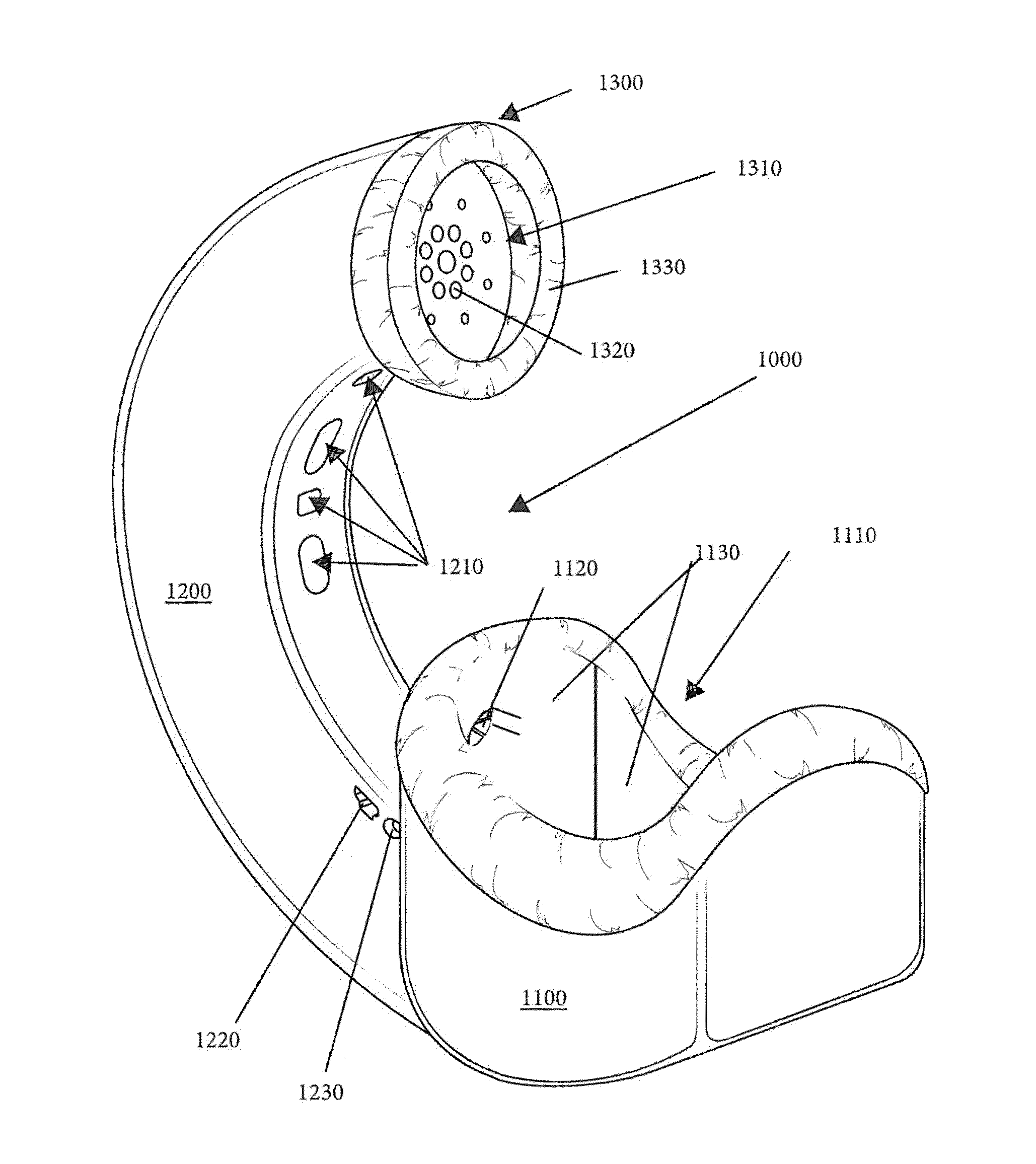
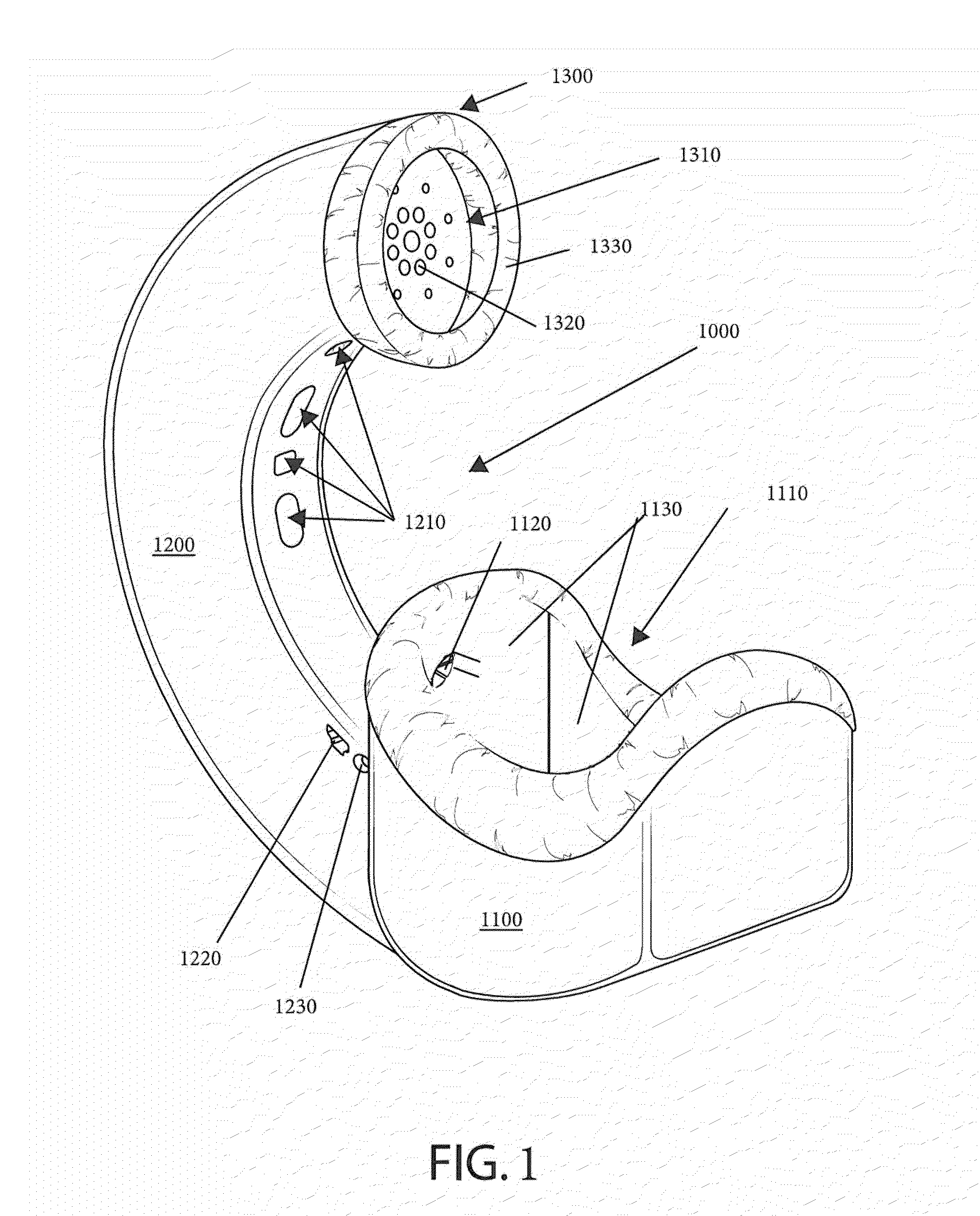
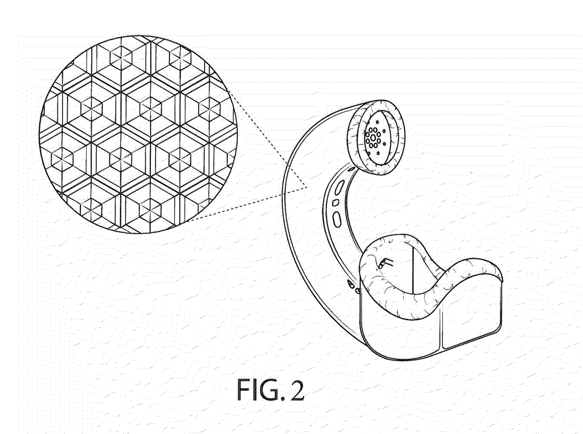
[0040]Disclosed, in general, are devices that provide an air-tight chamber over a sound source while trapping, containing, absorbing, directing and deflecting all fields of sounds from the sound source (e.g., the mouth of a human or a woodwind instrument). In general, the devices feature: a specialized anechoic chamber that is configured to receive a sound source in an air-tight manner; and a specialized anechoic channel that is in fluid communication with the ambient atmosphere. Suitably, the anechoic chamber is adapted to capture air containing sound energy generated by the sound source, and distribute the air about an internal surface area on the inside of the chamber, wherein the internal surface area is sufficiently large to dampen or otherwise absorb the sounds energy. Preferably, the air is directed from the anechoic chamber through an anechoic tubular channel extending therefrom to the ambient to further dampen or absorb the sound energy. In one configuration, the outer wall...


PUM


Abstract

Disclosed, in general, are devices that provide a substantially sound-tight chamber over a sound source while absorbing fields of sounds from the sound source. In general, the devices feature: an anechoic chamber that is configured to receive a sound source in a substantially sound-tight manner; and an anechoic channel that is in fluid communication with the ambient atmosphere. The anechoic chamber is adapted to capture air containing sound energy generated by the sound source, and distribute the air about an internal surface area on the inside of the chamber, wherein the internal surface area is sufficiently large to dampen or otherwise absorb the sound energy. Preferably, the air is directed from the anechoic chamber through an anechoic channel extending therefrom to the ambient to further dampen or absorb the sound energy. In one configuration, the outer wall of the apparatus is configured to reflect ambient sounds.

Description

CROSS-REFERENCE TO RELATED APPLICATIONS[0001]This application is a continuation-in-part to U.S. patent application Ser. No. 14 / 280,523 entitled “Ergonomic tubular anechoic chambers for use with a communication device and related methods” filed on May 16, 2014. This application also claims the benefit and priority of U.S. Prov. Pat. App. Ser. No. 61 / 949,239 (filed Mar. 7, 2014) entitled “Accessory having an anechoic chamber for isolating noise of a wind instrument.” This application further claims the benefit and priority of U.S. Pat. App. Ser. No. 61 / 949,234 (filed Mar. 6, 2014) entitled “Tubular Anechoic Chamber for use with a communication device.” Said patent applications are hereby incorporated by reference in their entirety as if fully set forth herein.STATEMENT REGARDING FEDERALLY SPONSORED RESEARCH OR DEVELOPMENT[0002]Not applicable.BACKGROUND OF THE INVENTION[0003]1. Field of Invention[0004]The subject matter of this written description is in the field of devices for contain...

Claims


Application Information

Patent Timeline
Patent Type & Authority Applications(United States)
IPC IPC(8): G10L21/0208H04R1/02H04M1/19H04R1/22
CPCH04M9/08H04R1/083H04R1/086H04R1/342H04R2499/11G10K11/16H04M1/19G10K11/002H04R1/02H04R1/225
Inventor MOSER, SCOTT A.
Owner QUIET
Why Eureka
Try Eureka