Radiolucent window, radiation detector and radiation detection apparatus

a radiation detector and radiation detection technology, applied in the direction of material analysis using wave/particle radiation, instruments, nuclear engineering, etc., can solve the problems of inability to transmit through the x-ray transmissive window and blockage of x-rays, and achieve the effect of reducing enhancing the detection efficiency of x-rays, and increasing the aperture ratio with respect to a specific incident direction

Active Publication Date: 2015-08-20
HORIBA LTD
View PDF2 Cites 15 Cited by
  • Summary
  • Abstract
  • Description
  • Claims
  • Application Information

AI Technical Summary

Benefits of technology

[0007]In an X-ray detection apparatus for detecting X-rays generated from a sample irradiated with radiation, e.g., an apparatus for detecting fluorescent X-rays, an X-ray detector is sometimes located close to a sample in order to enhance the detection efficiency of X-rays. In such an X-ray detection apparatus, X-rays enter obliquely with respect to an X-ray transmissive window. As the angle at which an X-ray enters the X-ray transmissive window becomes shallower, the probability that the X-ray is blocked by a rib of the X-ray transmissive window becomes higher, and thus the detection efficiency of the X-ray lowers. In a case where one point on a sample is irradiated with radiation and X-rays are detected, X-rays are generated from the one point on the sample and thus enter at a plurality of angles both in an in-plane rotation angle direction of the X-ray transmissive window and in an elevation angle with respect to the plane. Even in an X-ray transmissive window obtained by devising the form of a rib so that the aperture ratio with respect to a specific incident direction becomes higher, in a case where X-rays enter from a plurality of directions, a rib blocks X-rays entering from directions other than a direction in which the aperture ratio is made higher, and thus the detection efficiency of X-rays lowers.
[0008]The present invention has been made in view of such a situation, and the object thereof is to provide: a radiolucent window for effectively detecting radiation generated radially; a radiation detector; and a radiation detection apparatus.

Problems solved by technology

However, in a case where an X-ray enters obliquely with respect to an X-ray transmissive window, the X-ray is blocked by a rib and cannot be transmitted through the X-ray transmissive window.

Method used


Image

  • Radiolucent window, radiation detector and radiation detection apparatus
  • Radiolucent window, radiation detector and radiation detection apparatus
  • Radiolucent window, radiation detector and radiation detection apparatus

Examples


embodiment 1

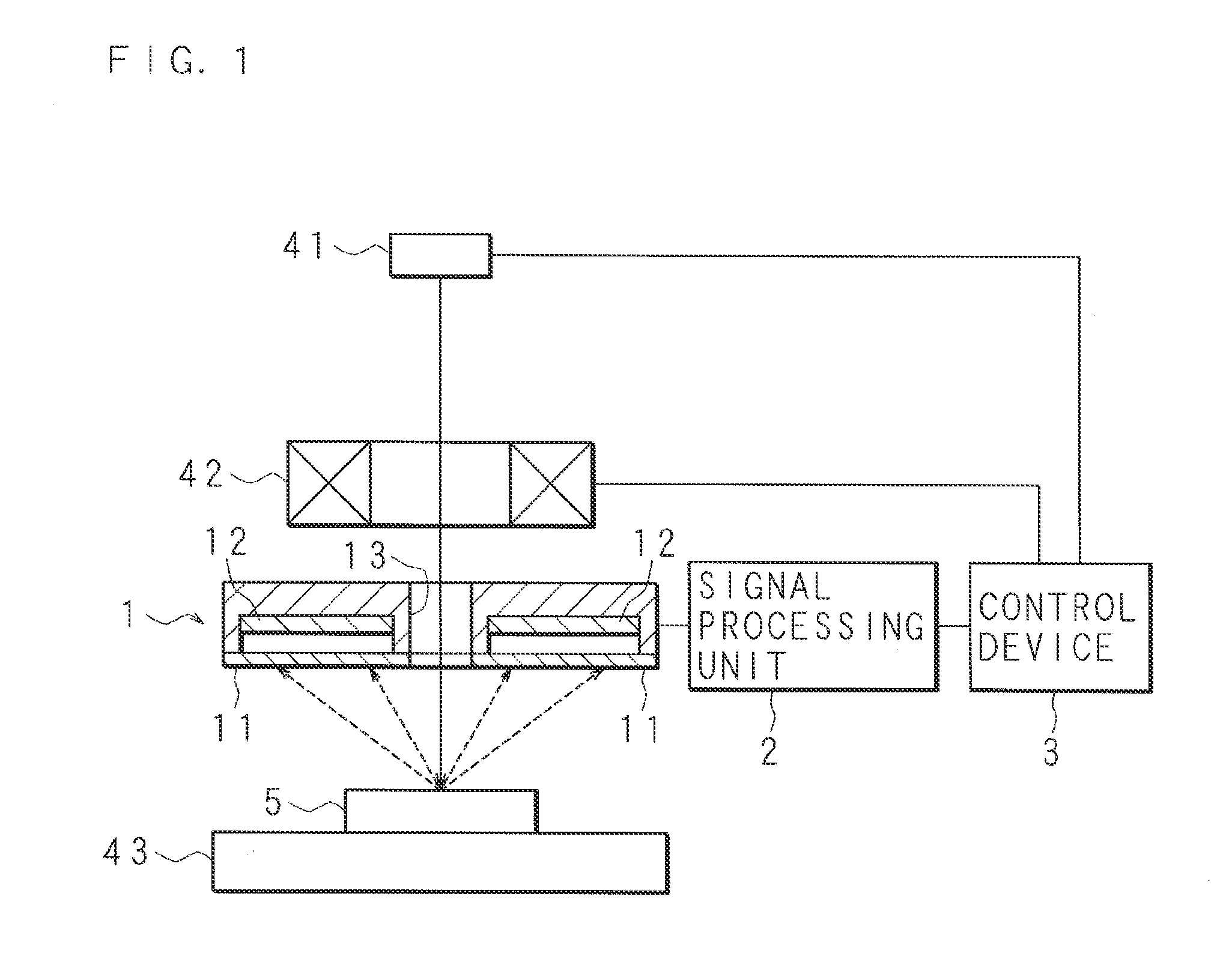
[0045]FIG. 1 is a block diagram illustrating the structure of an X-ray spectroscopic analyzer (radiation detection apparatus) according to Embodiment 1. The X-ray spectroscopic analyzer is provided with an electron gun 41 for irradiating a sample 5 with an electron ray (beam), an electron lens system 42, and a sample stage 43 on which the sample 5 is to be mounted. The electron lens system 42 includes a scanning coil which changes the direction of an electron ray. The electron gun (irradiation unit) 41 and the electron lens system 42 are connected with a control device 3 for controlling the entire X-ray spectroscopic analyzer.

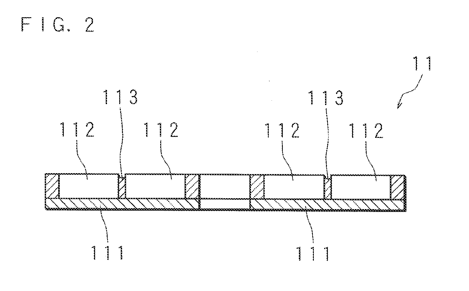
[0046]An X-ray detector (radiation detector) 1 is located between the electron lens system 42 and the sample stage 43. The X-ray detector 1 is formed to have a through-hole 13 which allows passage of an electron ray. FIG. 1 illustrates a section of the X-ray detector 1. Moreover, the X-ray detector 1 includes a plurality of X-ray detection elements 12, such as ...

embodiment 2

[0055]FIG. 5 is a schematic plan view of an X-ray transmissive window 11 according to Embodiment 2. A plurality of ribs in the X-ray transmissive window 11 include a plurality of linear ribs 112 formed radially with a center at a through-hole 13, and linear parallel ribs (fourth ribs) 117 formed parallel to the linear ribs 112. The X-ray spectroscopic analyzer has a structure similar to Embodiment 1 except the X-ray transmissive window 11.

[0056]The probability that the linear ribs 112 block characteristic X-rays entering the X-ray transmissive window 11 does not change according to the incidence angles of the characteristic X-rays as in Embodiment 1. Moreover, the parallel ribs 117 provide an effect equivalent to the linear ribs 112. That is, although the probability that the parallel ribs 117 block the characteristic X-rays becomes slightly higher as the incidence angles of the characteristic X-rays become shallower, the parallel ribs 117 are parallel to the linear ribs 112, and th...

embodiment 3

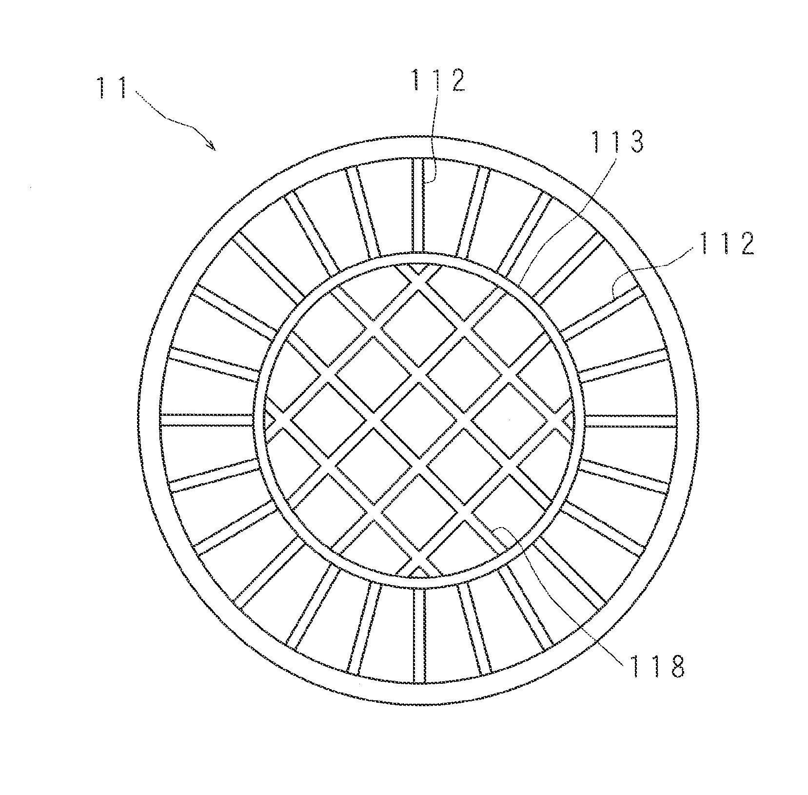
[0057]FIG. 6 is a schematic plan view of an X-ray transmissive window 11 according to Embodiment 3. A plurality of ribs in the X-ray transmissive window 11 include a plurality of linear ribs 112 formed radially with a center at a through-hole 13, an annular rib 113 formed to surround the through-hole 13, and a mesh rib 118 formed in a mesh form. The annular rib 113 is located so that the through-hole 13 is placed at the center thereof. Moreover, an X-ray transmissive film 111 includes a region (first region) closer to the through-hole 13 than the annular rib 113, and a region (second region) farer from the through-hole 13 than the annular rib 113. The linear ribs 112 are formed in the region farer from the through-hole 13 than the annular rib 113, and the mesh rib 118 is formed in the region closer to the through-hole 13 than the annular rib 113. The X-ray spectroscopic analyzer has a structure similar to Embodiment 1 except the X-ray transmissive window 11.

[0058]Since a region in t...


PUM

PropertyMeasurementUnit
heightaaaaaaaaaa
distanceaaaaaaaaaa
pressureaaaaaaaaaa

Abstract

Linear ribs are formed radially with a center at a through-hole on one face of an X-ray transmissive film (radiolucent film) in an X-ray transmissive window (radiolucent window) to be used for an X-ray detector (radiation detector). The X-ray transmissive window faces a sample. A beam for irradiation to the sample passes through the through-hole, and X-rays (radiation) are radially emitted on a line extending through the through-hole and enter the X-ray transmissive window. Since the linear ribs are formed radially with the center at the through-hole, even X-rays entering at shallow angles with respect to the X-ray transmissive window are transmitted through the X-ray transmissive window at a probability equivalent to X-rays entering at deep angles. More X-rays are transmitted through the X-ray transmissive window, and thus the X-ray detector can detect X-rays with high efficiency.

Description

CROSS-REFERENCE TO RELATED APPLICATION[0001]This Nonprovisional application claims priority under 35 U.S.C. §119(a) on Patent Application No. 2014-028671 filed in Japan on Feb. 18, 2014, the entire contents of which are hereby incorporated by reference.BACKGROUND[0002]1. Field of the Invention[0003]The present invention relates to: a radiolucent window, which transmits radiation entering a radiation detector; a radiation detector; and a radiation detection apparatus.[0004]2. Background Information[0005]Some X-ray detectors use a detection element, such as an SDD (Silicon Drift Detector), which requires cooling. For such an X-ray detector, vacuum sealing or dry gas enclosing is performed in order to prevent dew condensation in the detection element. Therefore, an X-ray detector is provided with an X-ray transmissive window, which transmits X-rays and can withstand a differential pressure between inside of the X-ray detector and the atmosphere. Conventional structures of an X-ray tran...

Claims


Application Information

Patent Timeline
Patent Type & Authority Applications(United States)
IPC IPC(8): G21K1/10G01N23/223
CPCH01J5/18H01J35/18H01J37/244H01J2237/24415G01N23/2252G01N23/223H01J37/3178H01J35/32G21K1/10
Inventor OHASHI, SATOSHINAKATA, YOSHIAKI
Owner HORIBA LTD
Why Eureka
Try Eureka