Antenna coil unit

a technology of antenna coil and coil unit, which is applied in the direction of battery/cell propulsion, engine-driven generator propulsion, transportation and packaging, etc., can solve the problems of reducing the strength of the magnetic field when the same electric power is imparted to the power-supply-side resonance coil, affecting the electromagnetic noise of electronic equipment or the like arranged around the coil unit, etc., so as to minimize the increase in the size of the antenna coil unit

Active Publication Date: 2015-08-20
EQUOS RES
View PDF3 Cites 6 Cited by
  • Summary
  • Abstract
  • Description
  • Claims
  • Application Information

AI Technical Summary

Benefits of technology

[0015]When the antenna coil unit is configured in this manner, the magnetic flux of the frequency component including the noise component, within the magnetic flux produced by the electric current flowing through the main coil, is drawn into the auxiliary coil and then returned to the main coil via the auxiliary coil. Specifically, the magnetic flux of the noise component generated by the main coil advances toward the auxiliary coil, which is arranged near enough that an induction current is produced due to the magnetic flux, without advancing a long distance. As a result, it is possible to suppress noise components located a long distance from the auxiliary coil as viewed from the main coil. The inspections, experiments, simulations, etc. performed by the inventor(s) have confirmed that a more pronounced noise-suppression effect is achieved when the resonance frequency of the auxiliary coil is set to a frequency that is shifted to a certain extent from the frequency of the noise component to be suppressed, rather than to the frequency of the noise component to be suppressed. The noise component having the most pronounced impact is often a harmonic component of the fundamental component of an electromagnetic wave produced by the electric current flowing through the main coil; the resonance frequency of the auxiliary coil preferably is a frequency that deviates from the harmonic component under predefined conditions. Thus, with the antenna coil unit according to the present invention, it is possible to suppress a noise component such as a harmonic component of the fundamental component of an electromagnetic wave produced by an electric current flowing through a main coil that functions as an antenna while minimizing the attenuation of the fundamental component.
[0017]In the antenna coil unit according to the present invention, as an example of one embodiment, the first reference axis and the second reference axis are preferably parallel. When the first reference axis and the second reference axis are parallel, the main coil and the auxiliary coil can be arranged on substantially the same plane; therefore, increases in the size of the antenna coil unit can be minimized.

Problems solved by technology

However, when power is supplied via magnetic field resonance, a magnetic field produced around a coil unit including a resonance coil (antenna coil) provided to the resonance circuit, the resonance coil serving as an antenna, may produce electromagnetic noise.
Electronic equipment or the like arranged around the coil unit may thereby be affected by the electromagnetic noise.
However, because the magnetic fields are counterbalanced, the strength of the magnetic field when the same electric power is imparted to the power-supply-side resonance coil is reduced, and the efficiency of power supply is also reduced.
However, in, e.g., wireless power transmission by magnetic field resonance, a pronounced noise-reduction effect is not necessarily obtained even when the frequency of the noise source and the resonance frequency of the noise-canceling resonance circuit are made to match in this manner; this problem is becoming apparent in the experiments, etc. performed by the inventor(s).

Method used


Image

  • Antenna coil unit
  • Antenna coil unit
  • Antenna coil unit

Examples


Embodiment Construction

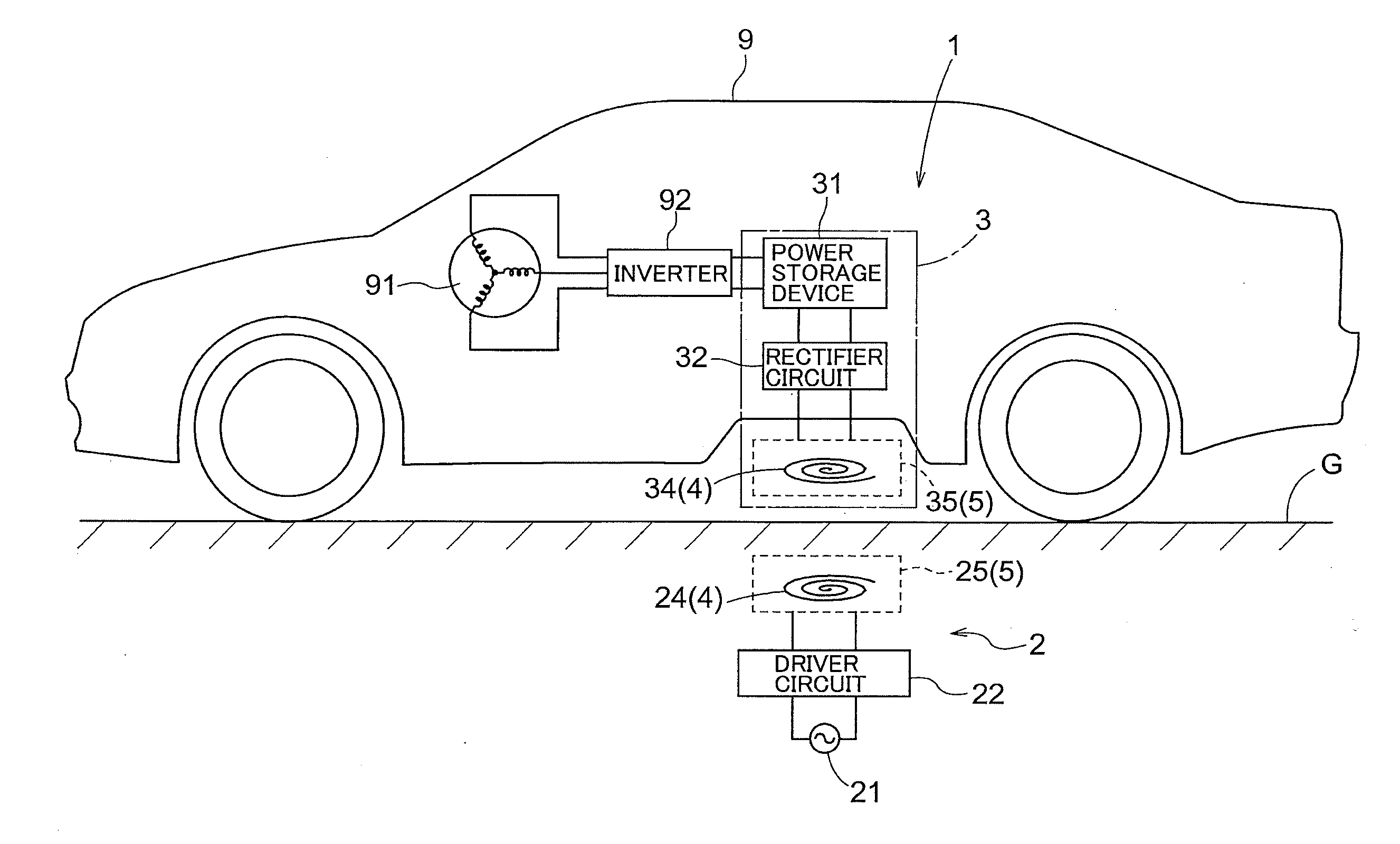
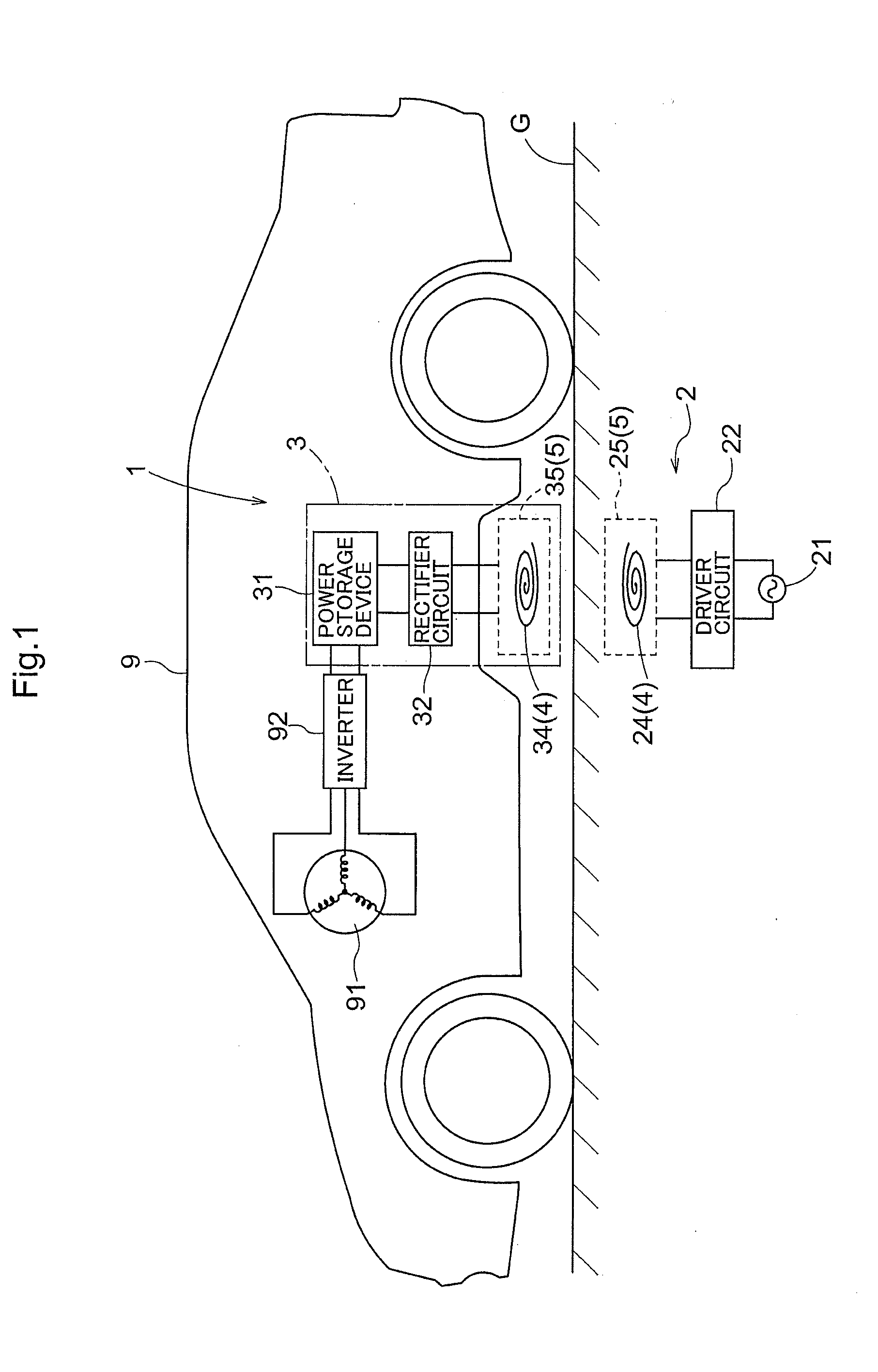
[0031]Embodiments of the present invention will be described below, as examples of a wireless power-supply system for using electromagnetic resonance coupling (referred to merely as “magnetic field resonance” below where appropriate) to perform wireless power supply (wireless power transmission) to a vehicle, with reference to the accompanying drawings. As shown in FIG. 1, a wireless power-supply system 1 (magnetic-field-resonance-type power supply device) is configured from a power-supply system 2 installed in a power-supply facility, and a power-receiving system 3 mounted in a vehicle 9. In the present embodiment, the power-supply system 2 is installed, e.g., near the ground G if the facility is outdoors, or near the floor if the facility is indoors.

[0032]As shown in FIG. 1, the power-supply system 2 is configured to have an AC power source 21, a driver circuit 22, and a power-supply-side resonance circuit 25. The power-supply-side resonance circuit 25 is configured to have a powe...


PUM

PropertyMeasurementUnit
resonance frequencyaaaaaaaaaa
magnetic fieldaaaaaaaaaa

Abstract

The antenna coil unit includes a main coil and an auxiliary coil electrically insulated from the main coil, the auxiliary coil being arranged at a position in which an induction current is produced by a magnetic field produced by an electric current flowing through the main coil. The auxiliary coil is configured in a state in which a frequency deviating by a predefined amount in a predefined direction from a target frequency predefined within a harmonic component of the fundamental component of an electromagnetic wave produced by the electric current flowing through the main coil is taken as a resonance frequency. The direction and amount are such that the phase of an alternating-current current flowing through the auxiliary coil is in an opposite-phase state, which is opposite the phase of the harmonic component of an AC current flowing through the main coil.

Description

TECHNICAL FIELD[0001]The present invention relates to an antenna coil unit for transmitting electric power or the like.BACKGROUND ART[0002]Cellular phones, personal digital assistants (PDAs), power-assisted bicycles, electric vehicles, hybrid vehicles, and other electrical devices and electromechanical apparatuses that are transportable without being left in one location have internal cells and other power storage devices so as to be capable of operating without being supplied by an external power supply. In many cases, charging of a power storage device is performed via a connection between a charge port provided to the device or apparatus and a power-supply device, interposed by a cable or the like. However, in recent years, there has been a demand for a technique for supplying electric power wirelessly without using such a cable, that is, without contact. In one technique for supplying electric power without contact, electromagnetic resonance coupling (referred to merely as “magn...

Claims


Application Information

Patent Timeline
Patent Type & Authority Applications(United States)
IPC IPC(8): H01F38/14H02J5/00H02J17/00B60L50/16H02J7/00
CPCH02J5/005H02J7/025H01F38/14H01F27/38B60L2210/30B60L2210/40B60L2240/36B60L2270/145B60L2270/147Y02T10/7072Y02T10/70Y02T90/14B60L50/16B60L50/51H02J50/12B60L53/122B60L53/126Y02T10/72H02J50/70Y02T90/12
Inventor YAMAKAWA, HIROYUKISATOU, KENICHIROU
Owner EQUOS RES
Why Eureka
Try Eureka