Dry Granulator

a technology of dry granulator and granule, which is applied in the direction of granulation by pressing, application, manufacturing tools, etc., can solve the problems of low granulating efficiency, unreliable sealing ability, and tight structure, and achieve high granulating efficiency, reliable sealing effect, and tight structure

Active Publication Date: 2015-08-27
ZHEJIANG FUTURE MACHINERY
View PDF1 Cites 30 Cited by
  • Summary
  • Abstract
  • Description
  • Claims
  • Application Information

AI Technical Summary

Benefits of technology

[0011]A main object of the present invention is to provide a dry granulator which is tight in structure, has reliable sealing effects for the feeding mechanism, has high granulating efficiency, and can produce high quality of finished particles products, has a low fine powder rate, is able to be applied to different kinds of mobile powders, and is easy to being automation production
[0012]Accordingly, all of the above mechanisms are arranged on a front of a machine body, wherein each of the mechanisms are compacted and working with a synergic motion, so as to achieve an automation production and to produce high quality of finished particles products, such that the dry granulator has high working efficiency and low fine powder rates, and the fine powder after screening by the sieving mechanism can be recycled, so as to be applied to a variety of mobile powder.
[0013]Preferably, the feeding cylinder is mounted at a horizontal angle of 10 to 30°, wherein there are two feeding screws arranged within the feeding cylinder, and a distance between two feeding screws is less than a total amount of radius of two feeding screws, and each of a top of the feeding screws is a conical structure. The above mentioned feeding device is suitable for different viscosity and mobility powder materials, so as to improve the feeding efficiency and working efficiency of the feeding device. The principle of the above mentioned structure is that: 1. the feeding cylinder is mounted at a horizontal angle to be applied to different viscosity and mobility of powder materials for preventing the diffusion of the powder materials. 2. The two feeding screws are able to improve a pushing pressure during a feeding motion, so as to improve the feeding efficiency. 3. The feeding screws are arranged in a small distance between each other to form a compacted structure, so while the two feeding screws are rotating in the same direction, the powder materials in the central portion between the two feeding screw generate a reactive larger friction force so as to push the powder materials to move forward quickly.

Problems solved by technology

Dry granulator is already provided on the market for many years, but due to various kinds technical limitations, the current dry granulator commonly has the disadvantages of having a tight-less structure, unreliable sealing abilities of feeding mechanism, low granulating efficiency, and providing low quality of finished particles products (refer to technical parameters of sheet weights, hardness, and disintegration), and also has a high fine powder rate.
Therefore, the current dry granulator cannot be applied to different kinds of mobile powders, and also have a difficult for being automation production.
According to the prior art, a position of the lower pressing wheel is fixed, and the upper pressing wheel is driven by two hydraulic pressure cylinders, a front hydraulic pressure cylinder and a rear pressure cylinder, to remain a radial clearance between the upper and lower pressuring wheel while the pressing mechanism is working A disadvantage of the above mentioned pressing mechanism is that the pushing force provided by the front and the rear hydraulic pressure cylinders will not fully balance, such that a front and rear end of pressing wheel shaft will produce different degrees of abrasion.
At the same time, while the hydraulic oil in the hydraulic pressure cylinder is compressed and released, a certain amount of oil gas inevitably separate out to contaminate the high quality requirement of a granulating environment.
Furthermore, since an axial position of the upper and lower pressing wheel is fixed and non-adjustable, so the height between an outer face end for the upper and lower pressing wheel has a certain degree of error, when the error exceeds 0.05 mm, the powder leakage phenomenon will generate on an area between the outer face end of the upper pressing wheel, the outer face end of the lower pressing wheel, and a cover arranged on the outer face end of the pressing wheel.
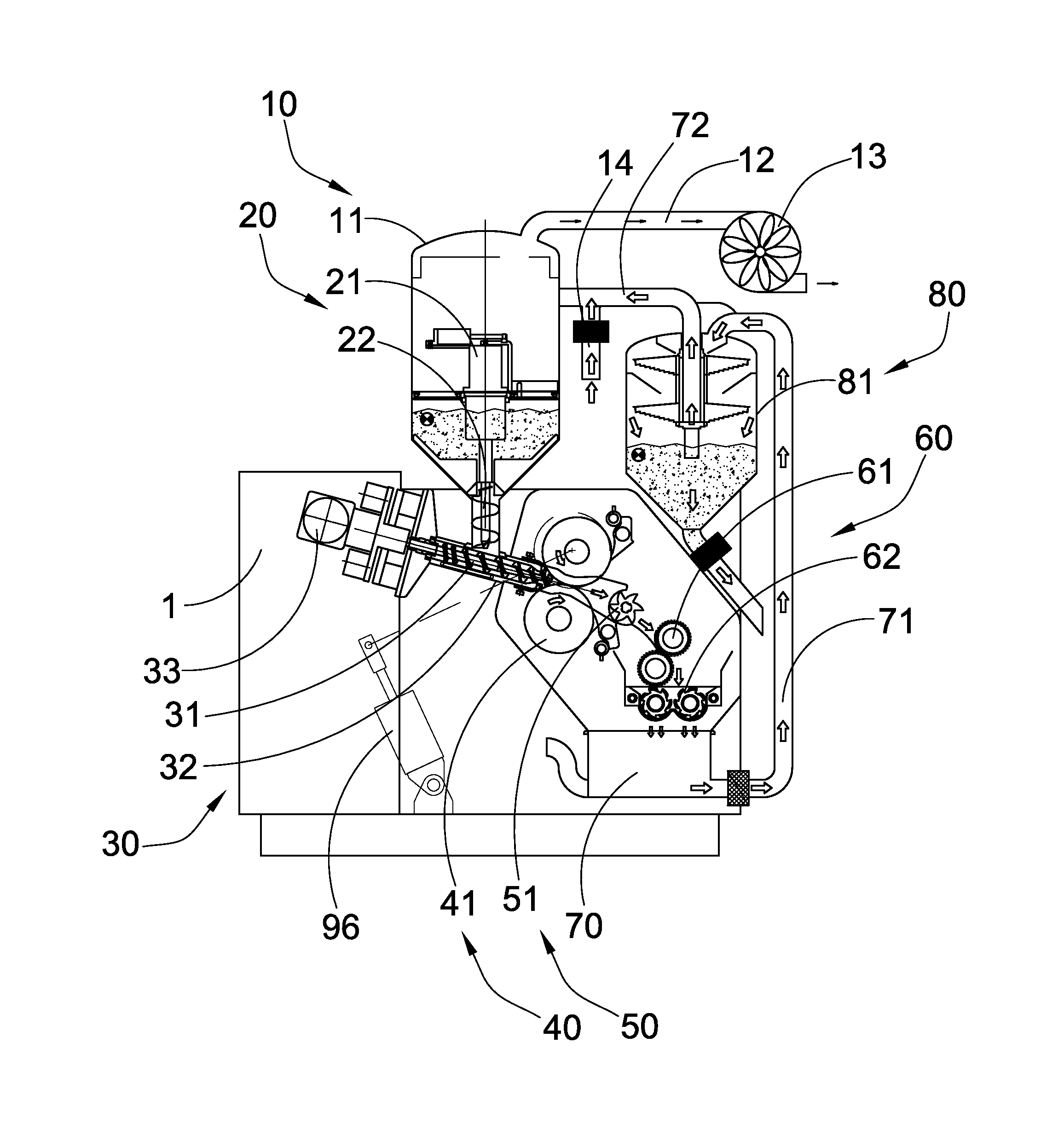
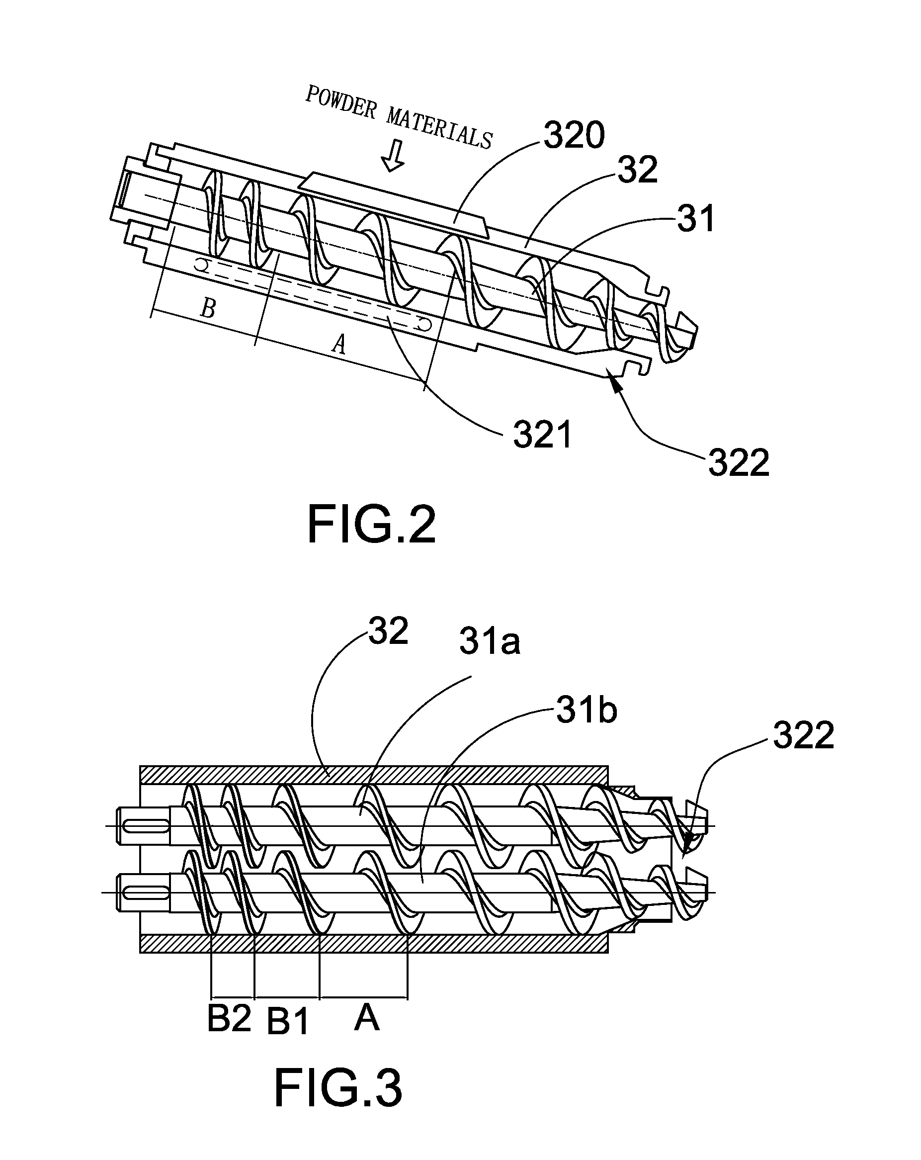
Moreover, the anti-leakage method for the feeding mechanism, which is adapted to prevent the powder materials leaking from the rear end of the feeding cylinder, is only by sealing the rear end of the feeding cylinder, but in the practical application process, the leakage problem is difficult to be solved, and especially for the good mobility materials.
Therefore, the anti-leakage method is an important technical problem for the current dry granulator.
Currently, the sieving mechanism for the dry granular on the current market commonly has the disadvantages of that the sieving efficiency is low, the purity of the finished particles is poor, and the fine powder rate of the finished products is high, especially in the sieving process, flying dusts will generate to cause the environmental pollution.
Although, the above filed patent application is able to solve the above mentioned problems, but in the actual trial process, while the fine powders pass through meshes of the sieving tray and fall down to the powder receiving tray, the fine powder will not gather toward a center of the powder receiving tray (the fine powder will be efficiently sucked out due to a large pressure difference between an outlet adjacent to the center of the powder receiving tray), such that the fine powder will gather away from the center of the powder receiving tray.
Currently, the crushing mechanism for dry granular on the market includes a swing structure, a granulating wheel, and a mesh wheel structure, but all of the crushing mechanisms have the following disadvantages: poor granulating effects, high fine powder rates, and low granulating efficiency.
Although, the patented technologies of the above China patent application is able to solve the above problems, but the structure of the granulating mechanism in the above China patent application is relatively complex.
Furthermore, the designs of the granulating wheel, the screen wheel, and the screen will cause low granulating effects, high fine powder rate, and low granulating efficiency.
But, in fact, it is very difficult to approach the two above mentioned sealing knife structures, wherein the sealing knife requires to be processed in high precision technology and the lifespan of the sealing knife will be reduced, and the sealing knife is very inconvenient to be assembled and disassembled.

Method used


Image

  • Dry Granulator
  • Dry Granulator
  • Dry Granulator

Examples


Embodiment Construction

[0049]Referring to FIG. 1 to FIG. 9 of the drawings, a dry granulator according to a preferred embodiment of the present invention is illustrated, wherein the dry granulator comprises a feeding mechanism 10, a vertical feeding mechanism 20, an oblique feeding mechanism 30, a pressing mechanism 40, a crushing mechanism 50, a granulating mechanism 60, a sieving mechanism 80, and a pressing wheel regulator 80, which are arranged on a front portion of a mechanism body 1.

[0050]The feeding mechanism 10 for a dry granular comprises a material tank 11 connected to a vacuum system, an exhaust fan 13, and a fan connection tube 12 connected with the material tank 11, wherein the vacuum system is working, the material tank 11 is in a vacuum situation, such that powder materials will be sucked from a sieving bucket 81 of the sieving mechanism 80 to the material tank 11. The vertical feeding mechanism 20 is arranged within the material tank 11, wherein the vertical feeding mechanism 20 comprises ...


PUM

PropertyMeasurementUnit
horizontal angleaaaaaaaaaa
heightaaaaaaaaaa
hardnessaaaaaaaaaa

Abstract

A dry granulator includes a feeding mechanism applied to suck powder materials into the material tanks; a vertical feeding mechanism to deliver the power materials to a bottom outlet of the material tank; a pressing mechanism to compress the powder materials into powder sheets with qualified hardness and thickness; an oblique feeding mechanism to deliver the powder materials to from the vertical feeding mechanism to the pressing mechanism; a crushing mechanism to crush the powder sheets into crushed powder sheets; a granulating mechanism to granulate the crushed powder sheet into finished particles products, so as to deliver to a collection storage; a sieving mechanism to separate the finished particle products with fine powders; a pressing wheel regulator applied to adjust an axial position of the lower and the upper pressing wheel; and a floating sealing device applied to provide a reliable sealing effect for the feeding mechanism.

Description

NOTICE OF COPYRIGHT[0001]A portion of the disclosure of this patent document contains material which is subject to copyright protection. The copyright owner has no objection to any reproduction by anyone of the patent disclosure, as it appears in the United States Patent and Trademark Office patent files or records, but otherwise reserves all copyright rights whatsoever.BACKGROUND OF THE PRESENT INVENTION[0002]1. Field of Invention[0003]The present invention related to a dry granulator, and more particularly to a dry granulator which is tight in structure, has reliable sealing ability of the feeding mechanism, has a high granulating efficiency, can provide high quality of finished particles products, has a low fine powder rate, is able to be applied to different kinds of mobile powders, and is easy to being automation production.[0004]2. Description of Related Arts[0005]Dry granulator is applied in the production of granular products, wherein the purpose of the dry granular is used ...

Claims


Application Information

Patent Timeline
Patent Type & Authority Applications(United States)
IPC IPC(8): B29B9/04B29B9/16
CPCB29B9/16B29B9/04B29B2009/168B01J2/22B02C2018/0061B02C23/14B02C23/38
Inventor LIN, DEPING
Owner ZHEJIANG FUTURE MACHINERY
Why Eureka
Try Eureka