Hollow poppet valve

a poppet valve and valve stem technology, applied in valve housings, machines/engines, transportation and packaging, etc., can solve the problems of inability to maintain the heat resistance of the valve head, inability to reduce the thickness of the wall indefinitely, and the valve head cannot achieve the effect of maintaining the heat resistance any longer, so as to improve the heat reduction property of the valve stem, reduce the total weight of the valve, and enhance the heat reduction property of the valv

Active Publication Date: 2015-08-27
NITTAN CORP
View PDF3 Cites 11 Cited by
  • Summary
  • Abstract
  • Description
  • Claims
  • Application Information

AI Technical Summary

Benefits of technology

[0047]According to the invention as recited in Claim 5, the entire coolant loaded in the valve stem cavity is positively stirred in response to a reciprocal motion of the valve in operation, thereby further enhancing the heat reduction property of the valve.
[0048]According to the invention as recited in Claim 6, the inner diameter of the stem-end side stem cavity may be increased and at the same time the step may be provided at an axially lower position in the valve stem cavity, thereby further improving the heat reduction property of the valve stem and reducing the total weight of the valve without influencing the durability of the valve. Thus, engine performance is further improved.

Problems solved by technology

The thickness of the wall, however, cannot be reduced indefinitely from the viewpoint of securing durability of the valve.
In actuality, however, it is hardly possible to do so since an excessive enlargement of the valve head cavity entails impermissible risk of thinning and weakening the valve head too much so that the valve head cannot maintain its heat resistance any longer.

Method used


Image

  • Hollow poppet valve
  • Hollow poppet valve
  • Hollow poppet valve

Examples


first embodiment

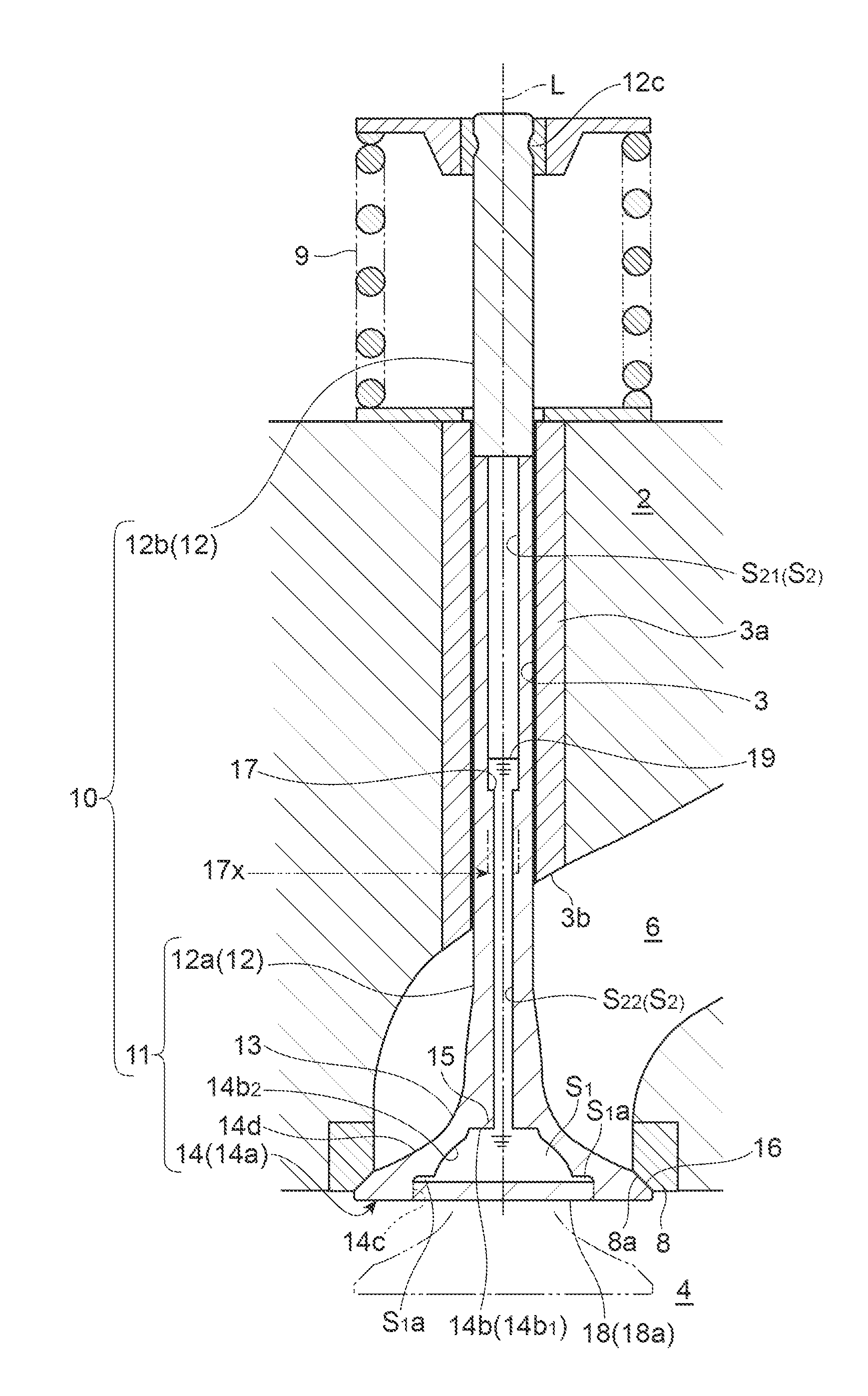
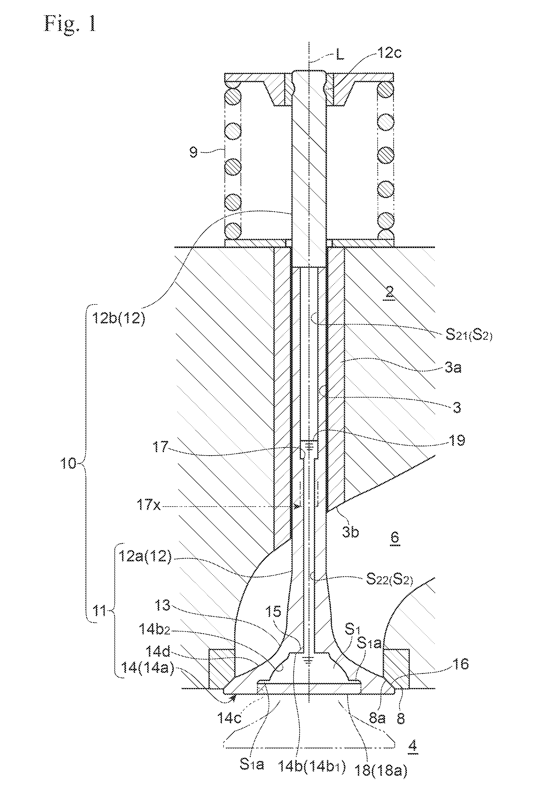
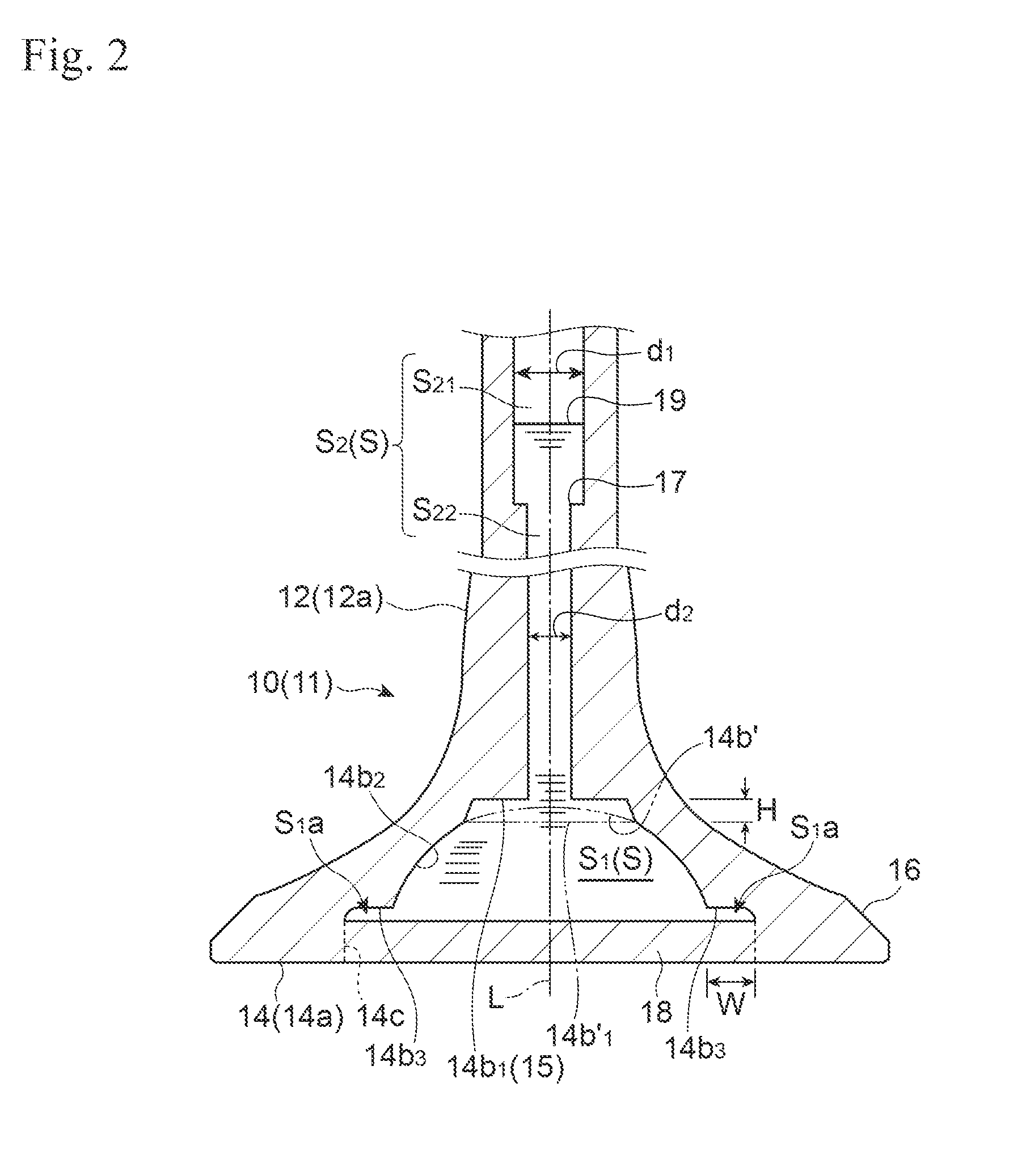
[0057]Referring to FIGS. 1 through 5, there is shown a hollow poppet valve for an internal combustion engine, in accordance with the invention.

[0058]In these figures, reference numeral 10 indicates a hollow poppet valve made of a heat resisting metal. The valve 10 has a straight valve stem 12 and a valve head 14 integrated with the valve stem 12 via a curved fillet 13 that has an increasing outer diameter. Provided in the peripheral region of the valve head 14 is a tapered seat 16 (also referred to as valve seat 16).

[0059]Specifically, an intermediate valve product 11 (hereinafter simply referred to as shell 11) comprises a generally cylindrical stem 12a and a valve head shell 14a integrally formed at one end of the stem 12a. A stem member 12b is welded to another end of the stem 12a, and a disk shape cap 18 is welded onto an inner periphery 14c of a generally truncated circular cone shape recess 14b of the valve head shell 14a to form a hollow poppet valve 10. The hollow poppet val...


PUM

PropertyMeasurementUnit
melting pointaaaaaaaaaa
shapeaaaaaaaaaa
distanceaaaaaaaaaa

Abstract

A hollow poppet valve (10) is provided with an additional flange shape cavity (S1a), in addition to an ordinary valve head cavity (S1) formed in the valve head (14) of the valve (10) in communication with a valve stem cavity (S2) formed in a valve stem (12). A coolant (19) is loaded in the cavities to facilitate dissipation of heat out of the valve. This flange shape cavity (S1a) extends radially outwardly round a bottom portion of the valve head cavity (S1), extending close to a valve seat, thereby significantly facilitating heat transfer between the coolant (19) and the valve seat of the valve, yet, since the flange shape cavity (S1a) does not influences the thickness of other regions of the valve, it does not degrade durability of the valve.

Description

TECHNICAL FIELD OF THE INVENTION[0001]This invention relates to a hollow poppet valve comprising an internal cavity extending from within a valve head into a valve stem and charged with a coolant, and more particularly to a hollow poppet valve comprising a diametrically large cavity formed in a valve head (the cavity hereinafter referred to as valve head cavity) communicated with a diametrically small cavity formed in a valve stem (the cavity hereinafter referred to as valve stem cavity).BACKGROUND ART OF THE INVENTION[0002]Patent Documents 1 and 2 listed below disclose hollow poppet valves comprising a valve head integrally formed at one end of a valve stem, the poppet valve formed with an internal cavity that extends from within a valve head into the valve stem and is charged with a coolant together with an inner gas, the coolant having a higher heat conductivity than the valve material. An example of such coolant is metallic sodium, which has a melting point of about 98° C.[0003]...

Claims


Application Information

Patent Timeline
Patent Type & Authority Applications(United States)
IPC IPC(8): F01L3/16F01L3/20F16K1/32
CPCF01L3/16F01L3/20F16K1/32F01L3/14B21K1/22B23P15/002Y10T137/6579F16K1/12F16K49/007F01L3/24F01P3/14
Inventor HOMMA, KOICHIONUMA, HIROKIHASEGAWA, JIN
Owner NITTAN CORP
Why Eureka
Try Eureka