
One-piece piston featuring additive machining produced combustion bowl rim and cooling gallery

a technology of additive manufacturing and pistons, which is applied in the direction of machines/engines, manufacturing tools, mechanical apparatus, etc., can solve the problems of high temperature and harsh conditions of operation, high cost of materials, and high labor intensity, and achieves reduced production time and cost, less waste of materials, and more practical and economical effects

Inactive Publication Date: 2015-09-03
TENNECO INC
View PDF11 Cites 27 Cited by
  • Summary
  • Abstract
  • Description
  • Claims
  • Application Information

AI Technical Summary

Benefits of technology

The invention provides a method to manufacture a practical and economical piston that can withstand extreme temperatures and conditions of a combustion chamber. The method includes forming a crown and skirt from a first material and creating a combustion surface along the crown from a second material using an additive machining process. This process reduces waste material and production time and costs. The piston has a combustion surface directly exposed to the conditions of the combustion chamber, which is formed from a high performance metal, while the bulk of the piston is formed from a more economical metal. The piston also includes a heat affected zone indicating that the additive machining process was used to form the combustion surface. This results in a cost-effective piston that can effectively withstand the harsh conditions of a combustion chamber.

Problems solved by technology

A piston used in internal combustion engines, such as a heavy duty diesel piston or light vehicle duty steel piston, is exposed to high temperatures and harsh conditions during operation, especially along the uppermost surface of the piston which faces a combustion chamber.
Exposure to the harsh conditions of the combustion chamber makes the piston susceptible to oxidation, erosion, and coking.
Unfortunately, such materials are typically expensive and therefore are oftentimes not a practical or economical option.

Method used


Image

  • One-piece piston featuring additive machining produced combustion bowl rim and cooling gallery
  • One-piece piston featuring additive machining produced combustion bowl rim and cooling gallery
  • One-piece piston featuring additive machining produced combustion bowl rim and cooling gallery

Examples


Embodiment Construction

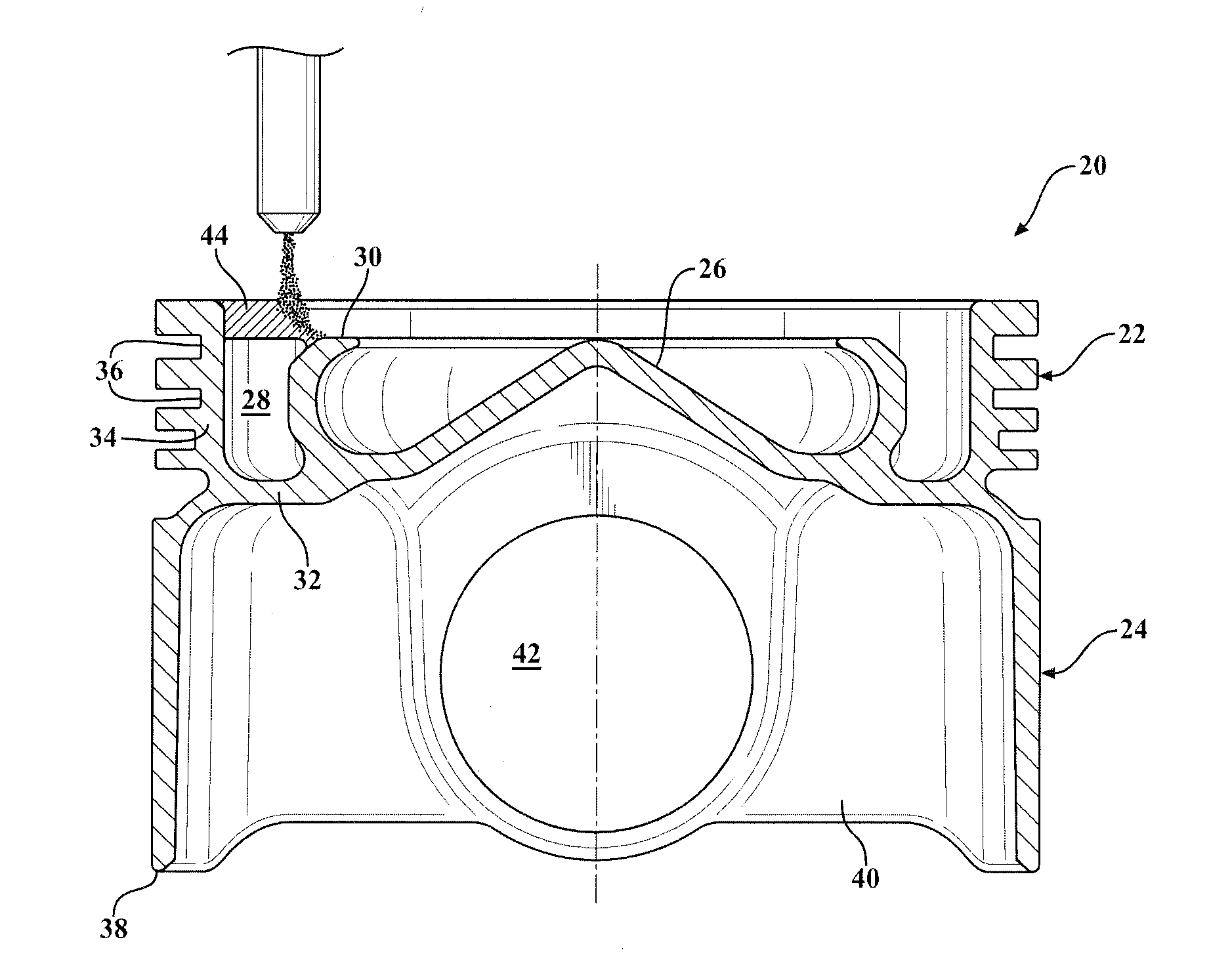
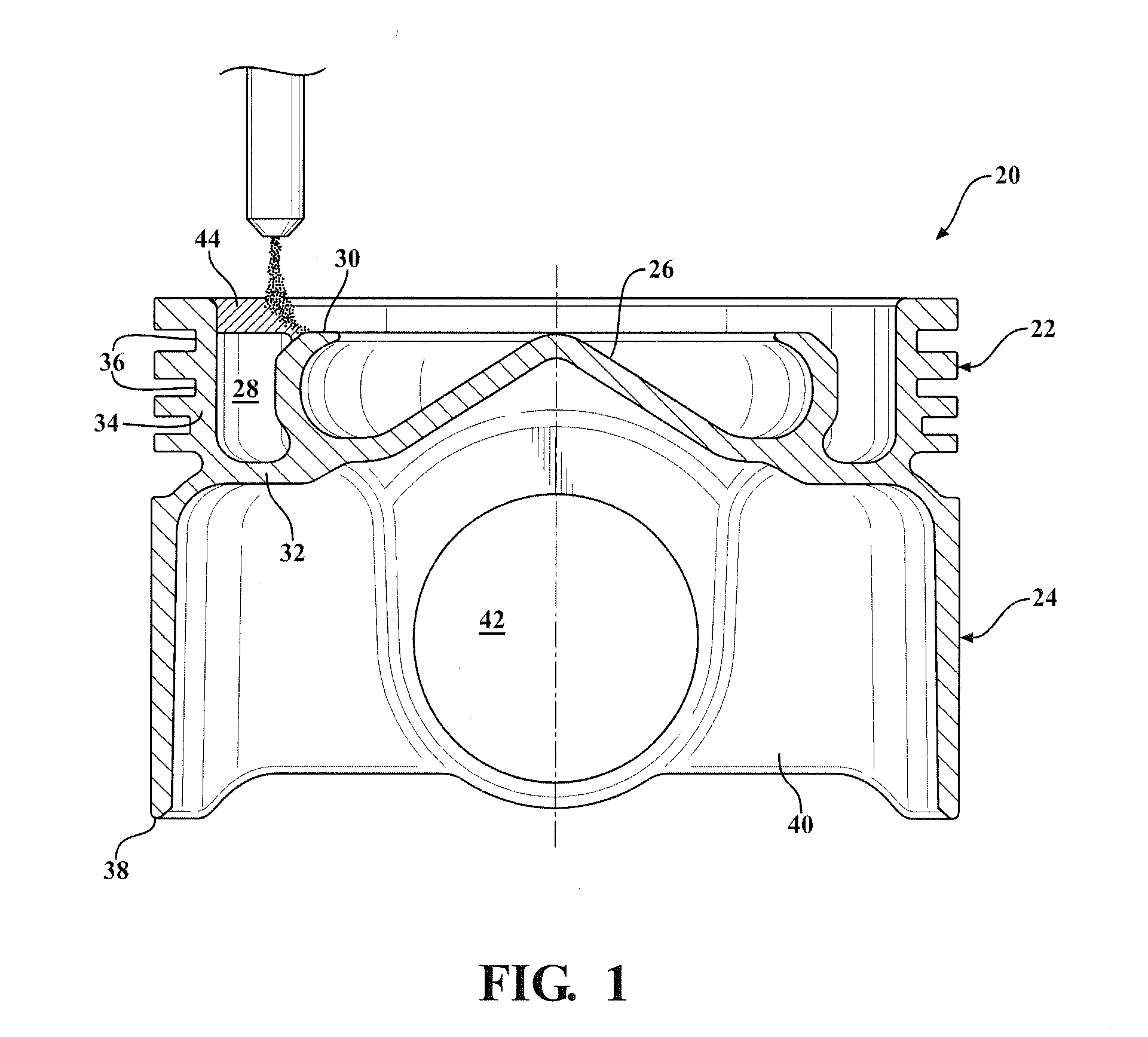
[0015]One aspect of the invention provides an economical method of manufacturing a piston 20 for use in an internal combustion engine which is capable of withstanding the high temperatures and harsh conditions of the combustion chamber with reduced production costs and complexity.

[0016]The method begins by forming the bulk of the piston 20, including a crown portion 22 and a skirt portion 24, as a single-piece from a first material. The first material is typically an economical metal material, such as steel, cast iron, a cast iron alloy, aluminum, or an aluminum alloy. The first material can include a single composition or a mixture of different metal compositions. A casting or forging process is preferably used to form the bulk of the piston 20 from the first material.

[0017]The piston 20 can comprise various different designs and geometries, depending on the type of piston and / or the engine for which the piston is designed. In the exemplary embodiment shown in FIGS. 1-3, the piston...


PUM

PropertyMeasurementUnit
velocityaaaaaaaaaa
areaaaaaaaaaaa
thermal conductivityaaaaaaaaaa

Abstract

A piston capable of withstanding high temperatures and extreme conditions of a combustion chamber of an internal combustion engine and manufactured with reduced costs is provided. The method of manufacturing the piston includes casting or forging the bulk of the piston as a single-piece with an open cooling gallery from an economical first material, such as steel, cast iron, or aluminum. The method further includes forming a portion of a combustion bowl surface, which is a small area of the piston directly exposed to the combustion chamber, from a second material by additive machining. The second material has a higher thermal conductivity and higher resistance to oxidation, erosion, and oil coking, compared to the first material. The additive machining process is efficient and creates little waste, which further reduces production costs.

Description

CROSS REFERENCE TO RELATED APPLICATION[0001]This U.S. utility patent application claims the benefit of U.S. provisional patent application No. 61 / 947,097, filed Mar. 3, 2014, the entire contents of which is incorporated herein by reference.BACKGROUND OF THE INVENTION[0002]1. Field of the Invention[0003]This invention relates generally to pistons for internal combustion engines, and methods of manufacturing the pistons.[0004]2. Related Art[0005]A piston used in internal combustion engines, such as a heavy duty diesel piston or light vehicle duty steel piston, is exposed to high temperatures and harsh conditions during operation, especially along the uppermost surface of the piston which faces a combustion chamber. Exposure to the harsh conditions of the combustion chamber makes the piston susceptible to oxidation, erosion, and coking. Therefore, the piston is typically designed with a cooling gallery beneath the uppermost surface. Cooling oil, or another cooling fluid, is typically c...

Claims


Application Information

Patent Timeline
Patent Type & Authority Applications(United States)
IPC IPC(8): F02F3/00B23P15/10C23C4/12B23K10/02B23K26/34B22F3/105F02F3/22B23K9/04
CPCF02F3/0084F02F3/22B23P15/10B23K9/044B23K10/027B33Y80/00B22F3/1055C23C4/12F02F2003/0007B33Y10/00B23K26/345F02F3/003B23K26/342C23C4/08C23C4/129B23K2101/003Y10T29/49263Y02P10/25B22F10/28B22F10/22
Inventor EVERS, ROSSKENNINGLEY, SCOTTCROMME, WOLFRAM
Owner TENNECO INC
Learn More