
Dynamic gain switching digital to analog converter

a digital to analog converter and dynamic gain technology, applied in the field of low noise digital to analog converters, can solve the problems of resistor noise, battery capacity limits available supply power and power consumption must be minimized, and electronic noise is inherent in all analog circuits

Active Publication Date: 2015-09-03
DSP GROUP
View PDF0 Cites 41 Cited by
  • Summary
  • Abstract
  • Description
  • Claims
  • Application Information

AI Technical Summary

Benefits of technology

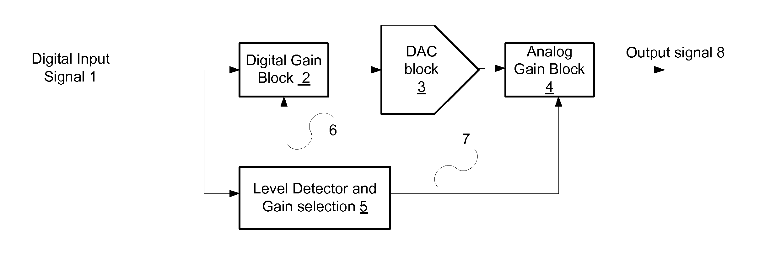
The patent describes a method and apparatus for digital to analog conversion. The method involves receiving a digital input signal, determining a digital gain factor and an analog gain factor, multiplying the digital input signal by the digital gain factor to provide an intermediate digital signal, converting the intermediate digital signal to a converted analog signal, and multiplying the converted analog signal by the analog gain factor to provide an output signal. The apparatus includes a digital to analog converter with a digital gain block, an analog gain block, a digital to analog conversion (DAC) block, and a controller. The controller determines the digital gain factor based on attributes of the digital input signal, such as level, amplitude, or derivative, and selects the appropriate digital amplifying path or adjusts the analog gain factor accordingly. The technical effects of the invention include improved accuracy and precision in digital to analog conversion and improved performance of the analog amplifying paths.

Problems solved by technology

Electronic noise is inherent in all analog circuits.
In mobile applications however, battery capacity limits available supply power and power consumption must be minimized.
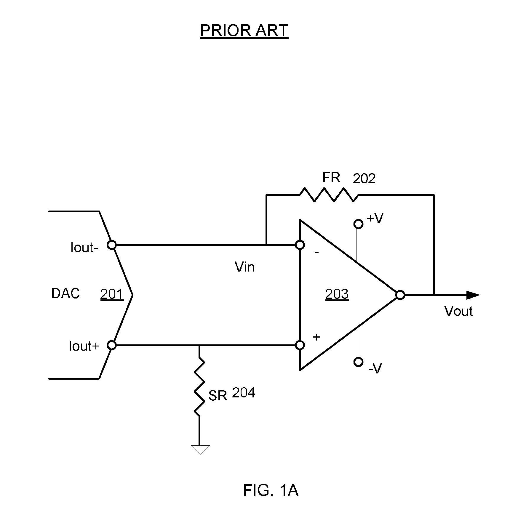
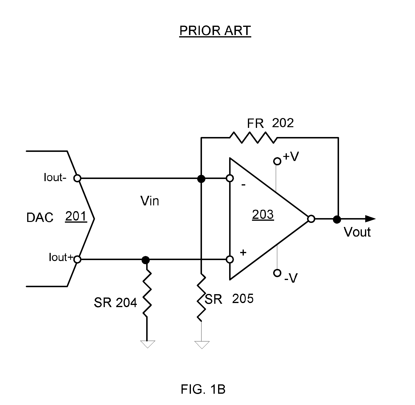
Second there is the resistor noise, thermal and flicker, which is related to the value of the transimpedance.
Third there is the amplifier input referred noise that is created primarily in the input stages of the amplifier and which is not related to the value of the transimpedance.
This results in a practical limit to the noise floor when limited by DAC and amplifier power consumption.
In many cases the DAC architecture also imposes similar limits on its output voltage range.
The problem is that increased voltage gain also amplifies the noise at the output of the amplifier.
The need to meet the gain criteria using the transimpedance amplifier effectively sets a limit on the noise levels and the result is that the desired noise levels and hence the signal to noise ratio of the output signal for state-of-the-art applications and devices is difficult to meet.
In other cases of DAC architectures such as voltage-mode DACs, similar noise analysis can be performed and similar design issues limit SNR

Method used


Image

  • Dynamic gain switching digital to analog converter
  • Dynamic gain switching digital to analog converter
  • Dynamic gain switching digital to analog converter

Examples


Embodiment Construction

[0048]In the following detailed description, numerous specific details are set forth in order to provide a thorough understanding of the invention. However, it will be understood by those skilled in the art that the present invention may be practiced without these specific details. In other instances, well-known methods, procedures, and components have not been described in detail so as not to obscure the present invention.

[0049]The subject matter regarded as the invention is particularly pointed out and distinctly claimed in the concluding portion of the specification. The invention, however, both as to organization and method of operation, together with objects, features, and advantages thereof, may best be understood by reference to the following detailed description when read with the accompanying drawings.

[0050]It will be appreciated that for simplicity and clarity of illustration, elements shown in the figures have not necessarily been drawn to scale. For example, the dimensio...


PUM


Abstract

A digital to analog converter that may include a digital gain block; an analog gain block; a digital to analog conversion (DAC) block and a controller that is configured to: determine a digital gain factor, selected out of multiple digital gain factors, of the digital gain block and an analog gain factor, selected out of multiple analog gain factors of the analog gain block; wherein the DAC block is preceded by the digital gain block and is followed by the analog gain block; wherein the digital gain block is configured to multiply a digital input signal by the digital gain factor to provide an intermediate digital signal; wherein the DAC block is configured to convert the intermediate digital signal to a converted analog signal; and wherein the analog gain block is configured to multiply the converted analog signal by the analog gain factor to provide an output signal; wherein an increment of the analog gain factor results in a decrement of the digital gain factor.

Description

RELATED APPLICATIONS[0001]This application claims priority from U.S. provisional patent Ser. No. 61 / 946,808, filing date Mar. 2, 2014 which is incorporated herein by reference.FIELD OF THE INVENTION[0002]This invention relates to the field of low noise digital to analog converters.BACKGROUND OF THE INVENTION[0003]Digital to analog converters (DAC) are used at the end of a digital processing chain where analog signal reproduction is required. Such uses include digital audio devices such as Compact Disc / MP3 players, HD radio and digital telephones. In all these applications, it is highly desirable to achieve a high signal to noise ratio (SNR) at the analog output while achieving the required, maximum high output signal level. In DAC applications, SNR is defined as the ratio between RMS of maximum amplitude output divided by the RMS of the integrated noise floor with no signal present and integrated within the frequency band of interest. SNR is usually specified in decibels (dB). For e...

Claims


Application Information

Patent Timeline
IPC IPC(8): H03M1/70H03M1/08H03M1/00
CPCH03M1/70H03M1/0845H03M1/002H03M1/662
Inventor ELYADA, ORI
Owner DSP GROUP
Learn More