Expanded gas power plant for energy storage

a gas power plant and energy storage technology, applied in steam engine plants, machines/engines, mechanical equipment, etc., can solve the problems of insufficient storage and power ratio, power plant no longer being able to provide these network services, system power loss, etc., to improve the use of waste heat, improve the effect of energy storage efficiency and good degree of flexibility in power plant installation

Inactive Publication Date: 2015-09-10
SIEMENS AG
View PDF5 Cites 3 Cited by
  • Summary
  • Abstract
  • Description
  • Claims
  • Application Information

AI Technical Summary

Benefits of technology

[0009]The present invention is hence based on an object of avoiding these drawbacks known from the prior art, and proposing temporary storage of electrical current from the public supply networks which is both efficient in terms of the power balance and also possible with respect to technical realization without great expenditure. In particular, an object is to include making improved use of the waste heat, while in particular a good degree of flexibilization of the power plant installation should be achieved at the same time. Furthermore, the present invention should make it possible to temporarily store electrical power drawn from the public supply networks, which can be effected without cost-intensive changes on the basis of already-installed power plants. It is in addition an object of the invention to modify existing power plant installations such that they are improved in terms of their flexibilization.

Problems solved by technology

The rapid roll-out of renewable energy sources, which typically feed into the public supply network electrical power which varies markedly over time, has resulted in numerous challenges with respect to network stability and with respect to the measures necessary to achieve this network stability.
However, it is already apparent that in the future a number of these power plants will no longer be capable of providing these network services, as they will have to be operated at ever-diminishing capacity.
A disadvantage of such temporary storage is, however, that every storage procedure, or the attendant energy conversion processes, results in a loss of power caused by the system.
As a consequence, many of the solutions for the temporary storage of excess electrical current which are currently known and have been discussed up to now suffer from a storage and power ratio that is not sufficiently efficient.
However, a disadvantage of such an approach is that the use of the waste heat is still not sufficiently efficient.
Equally, the installation known from the prior art cannot achieve the degree of flexibilization of a power plant installation that is currently required.

Method used


Image

  • Expanded gas power plant for energy storage
  • Expanded gas power plant for energy storage
  • Expanded gas power plant for energy storage

Examples


Embodiment Construction

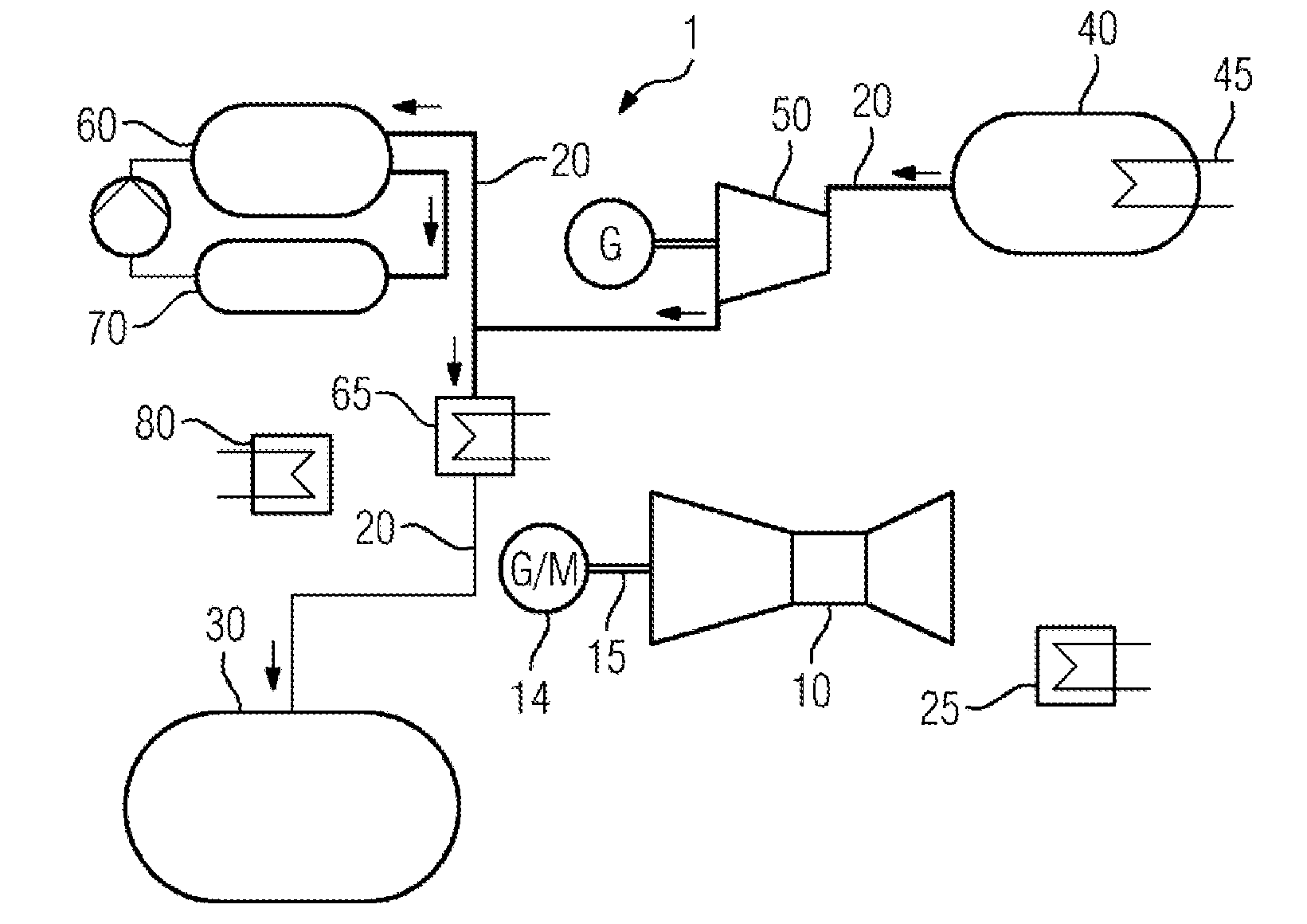
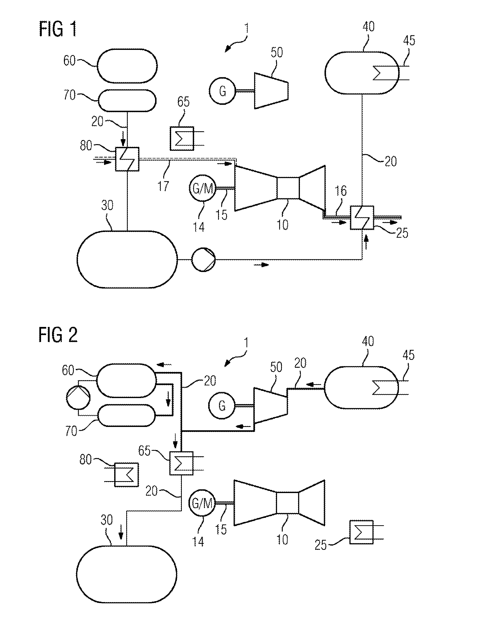
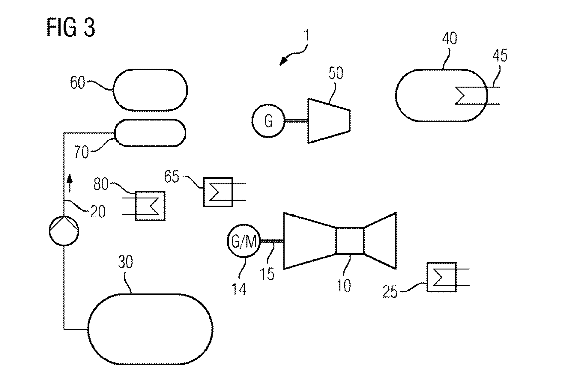
[0041]FIG. 1 shows a schematic representation of individual processes in an embodiment of a gas power plant 1 according to the invention during charging operation. According to this, a gas turbine 10 of a gas power plant 1, which is connected via a shaft 15 to a generator 14 which can also be operated as a motor, is operated as a motor by the generator 14. In this context, the intake air 17 is first compressed—essentially adiabatically—in a compressor section of the gas turbine 10, wherein the temperature of the intake air 17 so compressed is increased. It is also possible, according to the embodiment, that fuel is supplied to the combustion chamber of the gas turbine 10 in order to further raise the temperature, which fuel is burnt as the compressed air passes through the combustion chamber. The combustion heat thus produced is transferred to the exhaust gas and raises the temperature and heat content thereof. Upon exiting the gas turbine, this air, treated in this manner, conseque...


PUM


Abstract

A method for operation of a gas power plant, and to a gas power plant of this type, comprising a gas turbine, which is connected to a generator that can also be operated as a motor and which is thermally coupled to a water vapour circuit by way of a first heat exchanger are provided. The method includes: operating the generator as a motor in such a way that a heated gas flow is discharged from the gas turbine; thermally treating of water in the water vapour circuit via the first heat exchanger by the heated gas flow; storing of the water thermally treated in this way in a vapour accumulator; operating a steam turbine with water vapour taken from the vapour accumulator; diverting of the water vapour after interaction with the steam turbine into a vapour chamber for condensation; and collecting of the condensed water in a condensate reservoir.

Description

CROSS REFERENCE TO RELATED APPLICATIONS[0001]This application is the US National Stage of International Application No. PCT / EP2013 / 062743 filed Jun. 19, 2013, and claims the benefit thereof. The International Application claims the benefit of European Application No. EP12184832 filed Sep. 18, 2012. All of the applications are incorporated by reference herein in their entirety.FIELD OF INVENTION[0002]The present invention relates to a method for operating a gas power plant, comprising a gas turbine which is connected to a generator that can also be operated as a motor, and which is thermally coupled to a steam circuit via a first heat exchanger. The present invention also relates to such a gas power plant.BACKGROUND OF INVENTION[0003]The rapid roll-out of renewable energy sources, which typically feed into the public supply network electrical power which varies markedly over time, has resulted in numerous challenges with respect to network stability and with respect to the measures n...

Claims


Application Information

Patent Timeline
Patent Type & Authority Applications(United States)
IPC IPC(8): F02C6/14F01K3/00F01K23/10F02C6/18
CPCF02C6/14F01K23/10F01K3/00F02C6/18F01K3/02F05D2220/62Y02E20/14
Inventor BRUNHUBER, CHRISTIANKNOBLOCH, KATJAMENAPACE, WOLFGANGSTROBELT, FRANKVORTMEYER, NICOLASZIMMERMANN, GERHARD
Owner SIEMENS AG
Why Eureka
Try Eureka