
Actuating unit for variable power plant components

a technology of variable power plant components and actuation units, which is applied in the direction of engine controllers, machines/engines, connecting rods, etc., can solve the problems of damage to constructional parts and the disadvantage of still necessitating relatively extensive modifications on an otherwise existing engin

Inactive Publication Date: 2015-09-17
FEV
View PDF2 Cites 19 Cited by
  • Summary
  • Abstract
  • Description
  • Claims
  • Application Information

AI Technical Summary

Benefits of technology

The patent is about a new type of engine that uses a variable compression technology to improve its performance. The engine has a special actuating unit that can change the compression of the engine by adjusting the length of a connecting rod, the height of a piston, or the radius of a crankshaft. The actuating unit is located lower than the engine, making it easier to assemble. The engine is also designed in a more compact way, reducing its size. The actuating unit uses a switching element that can move parallel to the crankshaft, and a cam disk unit that can be easily manufactured and assembled. The forced displacement of the switching element is set to at least 50% of its nominal displacement, and can be adjusted to account for any tolerances in the cam disk unit or in its positioning relative to the switching element. Overall, this technology allows for improved engine performance and reduced size.

Problems solved by technology

In experimental tests, it has become evident that an adjustment from one to another end position e.g. of an eccentric element in the small connecting rod eye, although it can be realized within a working cycle, involves the possibility of damage to the constructional parts when a mechanical end abutment is reached.
This manner of actuation has the disadvantage of still necessitating relatively extensive modifications on an otherwise already existing engine, particularly on the cylinder crank housing.

Method used


Image

  • Actuating unit for variable power plant components
  • Actuating unit for variable power plant components
  • Actuating unit for variable power plant components

Examples


Embodiment Construction

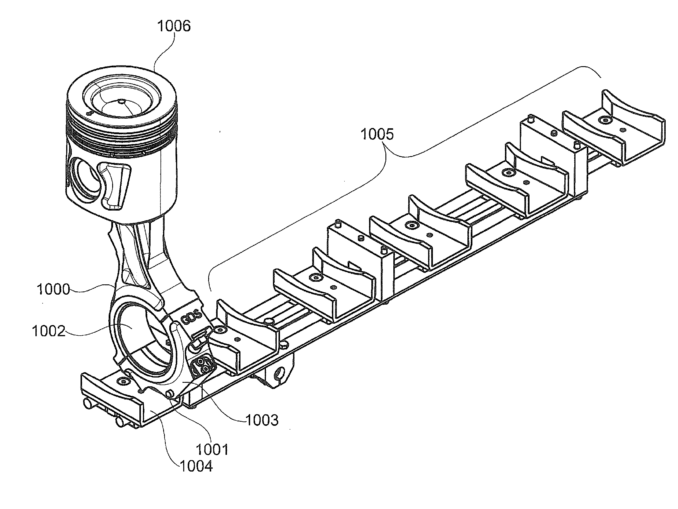
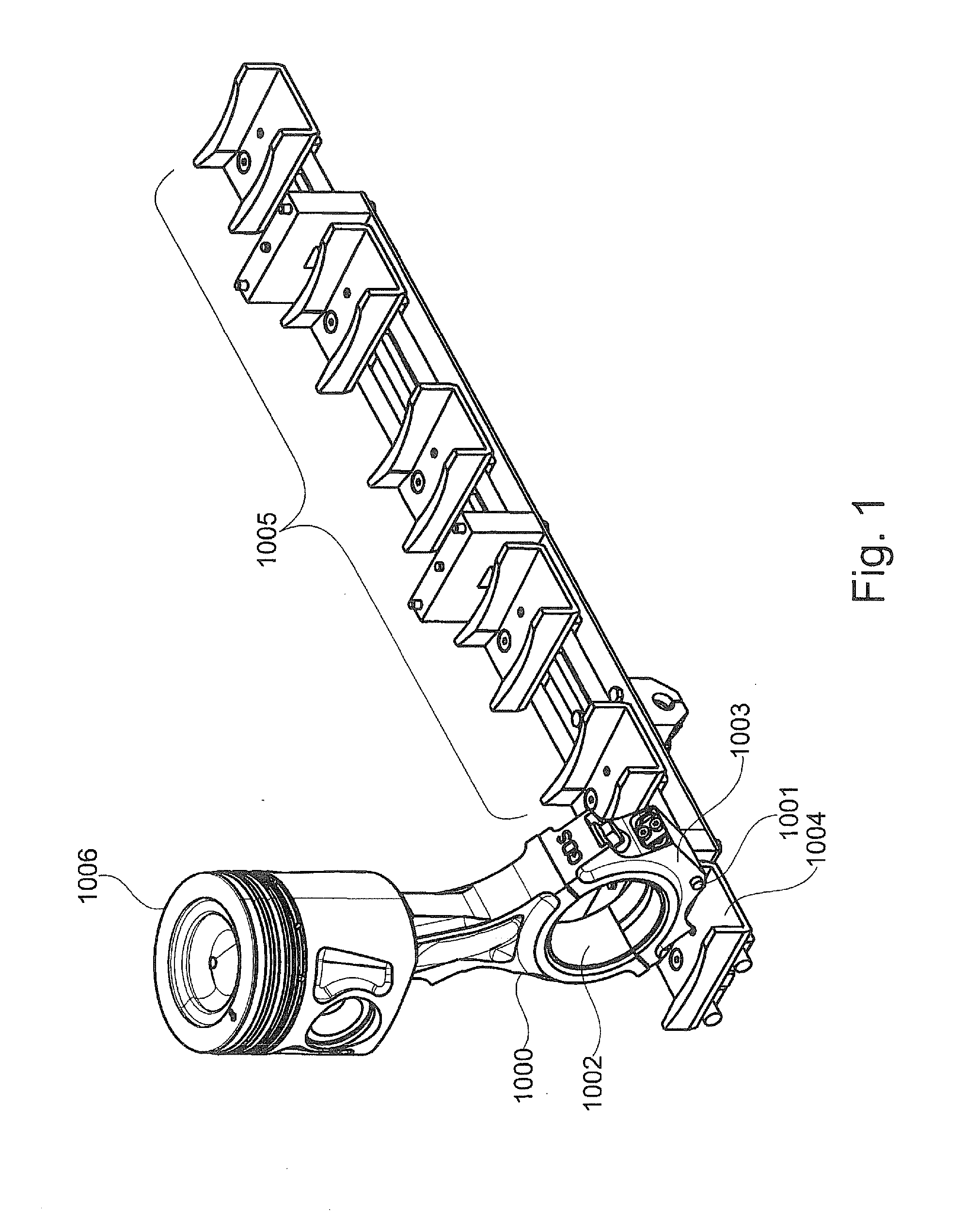
[0046]FIG. 1 shows a connecting rod 1000 wherein a switching element 1001 is arranged on the large connecting-rod eye 1002. An adjustment device for adjusting a compression ratio that can be varied by setting, is arranged on the small connecting-rod eye of connecting rod 1000. In FIG. 1, this adjustment device is hidden from view by a piston 1006. Particularly, the switching element 1001 can be integrated into the connecting-rod cap 1003. Further, a cam disk element 1004 for operating the switching element 1001 can be arranged below the crankshaft of the reciprocating-piston internal combustion engine. Particularly, for each connecting rod of a cylinder of the reciprocating-piston internal combustion engine, there is provided a respective cam disk element. The individual cam disk elements of the respective cylinders are preferably combined into a prefabricated module 1005. The module 1005 shown in FIG. 1 is provided for a 6-cylinder in-line engine.

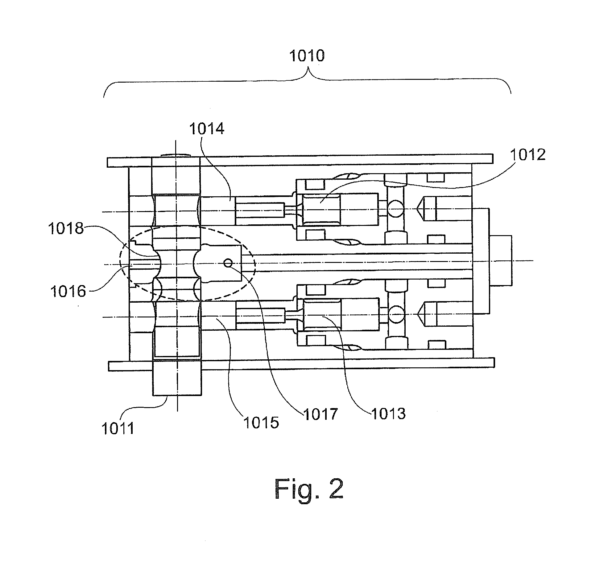
[0047]FIG. 2 shows a hydraulic way ...


PUM

PropertyMeasurementUnit
Lengthaaaaaaaaaa
Lengthaaaaaaaaaa
Fractionaaaaaaaaaa

Abstract

The invention relates to a reciprocating-piston internal combustion engine with variable compression, having an actuating unit for changing a variable compression of the reciprocating-piston internal combustion engine, wherein, to change the variable compression, the actuating unit actuates a variable engine component of the reciprocating piston internal combustion engine in the form of a connecting rod with variable length, a piston with variable compression height and / or a crankshaft with variable crankshaft radius, and the actuating unit is arranged at a lower level than the reciprocating-piston internal combustion engine. Also proposed are a method and also an actuating unit for the same.

Description

CROSS-REFERENCE TO RELATED APPLICATIONS[0001]This application is the U.S. national phase of PCT / EP2013 / 002256 filed Jul. 30, 2013, which claims priority of German Patent Application 10 2012 014 918.2 filed Jul. 30, 2012, the entire contents of which are incorporated herein by reference.FIELD OF THE INVENTION[0002]The invention relates to a reciprocating-piston internal combustion engine with variable compression, having an actuating unit for changing a variable compression of the reciprocating-piston internal combustion engine, an actuating unit preferably for the proposed reciprocating-piston internal combustion engine, and a method for adapting a variable compression of a reciprocating-piston internal combustion engine, It is proposed to make it possible to use, herein, different variable engine components, namely[0003]connecting rod of variable length,[0004]piston with variable compression height,[0005]crankshafts with variable crank radius.[0006]These all are intended, inter ali...

Claims


Application Information

Patent Timeline
IPC IPC(8): F02D15/02F02B75/24F02B75/04
CPCF02D15/02F02B75/045F02D2700/03F02B75/044F02B75/243F02B75/047F02B75/04F16C7/06Y10T29/49233
Inventor WITTEK, KARSTEN
Owner FEV
Learn More