
Touch-sensitive display device

a display device and touch technology, applied in the field of touch-sensitive display devices, can solve the problems of inability to implement transparent and electrically-conductive materials used for touch electrodes, such as ito (indium tin oxide), and defects in flexible display, so as to achieve lower flexibility, higher resistance, and the effect of reducing the flexibility

Active Publication Date: 2015-09-17
LG DISPLAY CO LTD
View PDF28 Cites 48 Cited by
  • Summary
  • Abstract
  • Description
  • Claims
  • Application Information

AI Technical Summary

Benefits of technology

The present disclosure is about a touch-sensitive display device that uses ITO as the material for its touch electrodes, but has higher resistance and lower flexibility compared to metal materials, which can result in cracks and flexibility issues when the device is bent. The disclosure aims to provide a solution to reduce power consumption, minimize cracks, and increase touch sensitivity for a large touch-sensitive display device. The device may also include an anti-oxidation layer to reduce oxidation of the metal electrodes.

Problems solved by technology

Transparent and electrically-conductive materials used for touch electrodes, such as ITO (indium tin oxide), are not appropriate to be implemented in a flexible display because they are less flexible than typical metal materials.
Therefore, if a touch-sensitive display device that uses ITO as the material for its touch electrodes is applied to a flexible display, cracks may occur in the ITO.
This may result in defects in the flexible display.
In addition, due to ITO's higher resistance than that of metal materials, power consumption increases as a touch-sensitive display device becomes larger.
Also, touch sensitivity is significantly decreased in the center portion of the display device which in return causes a slower response speed.

Method used


Image

  • Touch-sensitive display device
  • Touch-sensitive display device
  • Touch-sensitive display device

Examples


Embodiment Construction

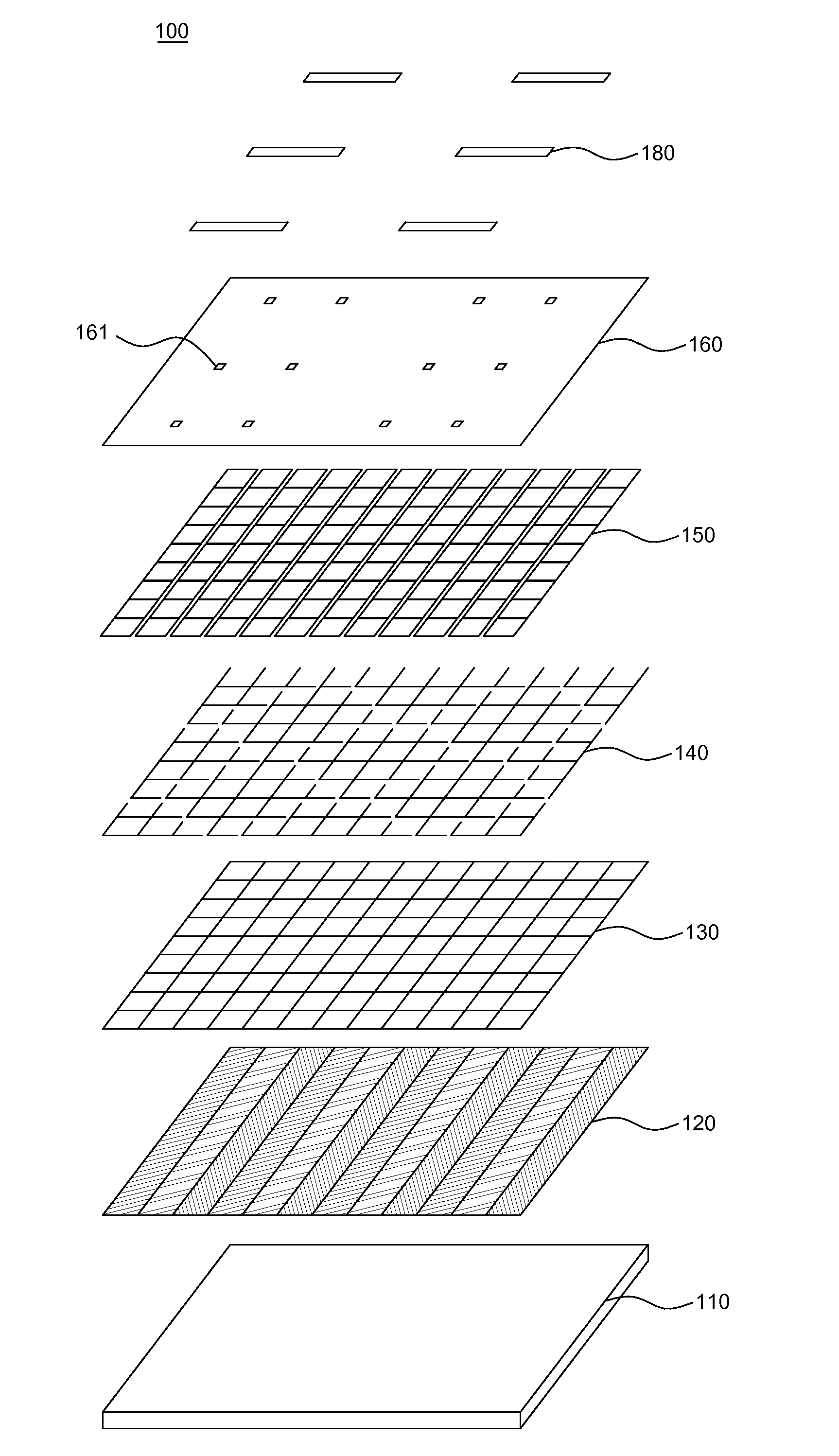
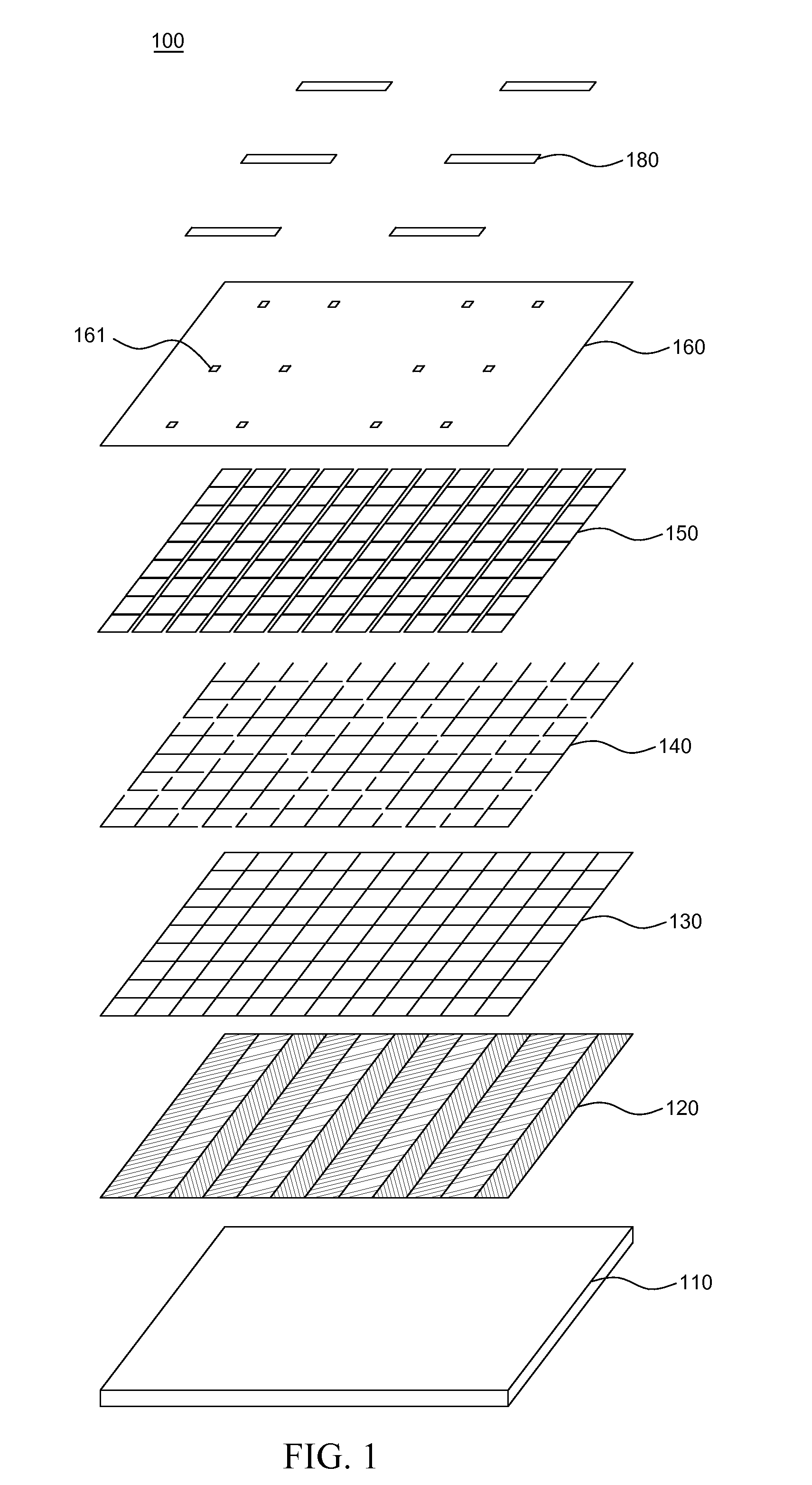
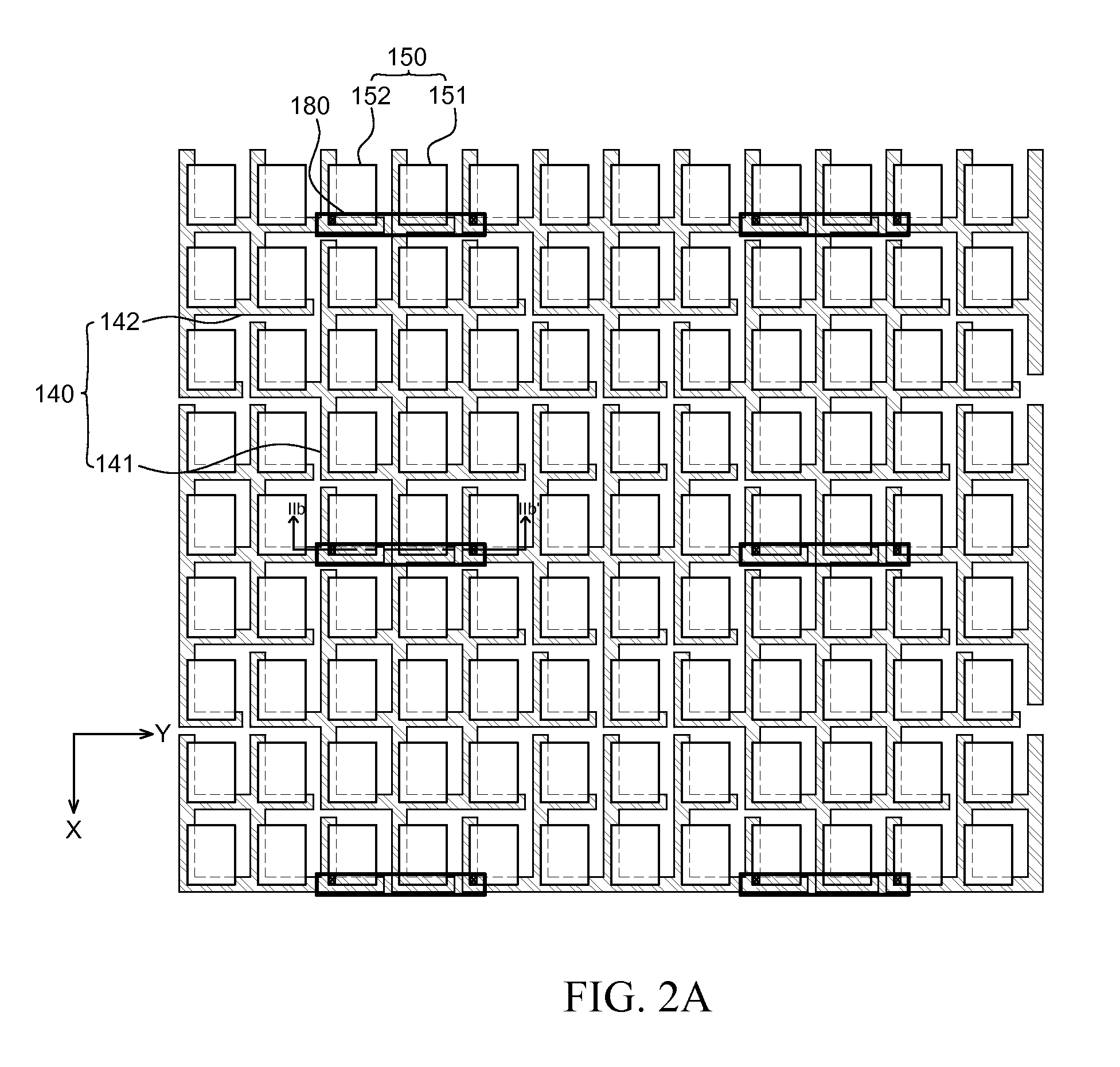
[0047]Advantages and features of the present disclosure and methods to achieve them will become apparent from the descriptions of exemplary embodiments herein below with reference to the accompanying drawings. However, the present disclosure is not limited to exemplary embodiments disclosed herein but may be implemented in various different ways. The exemplary embodiments are provided for making the disclosure thorough and for fully conveying the scope of the present invention to those skilled in the art. It is to be noted that the scope of the present invention is defined only by the claims.

[0048]The figures, dimensions, ratios, angles, numbers of elements given in the drawings are merely illustrative and are not limiting. Like reference numerals denote like elements throughout the descriptions. Further, in describing the present invention, descriptions on well-known technologies may be omitted in order not to obscure the gist of the present invention. It is to be noticed that the ...


PUM


Abstract

Disclosed herein is a touch-sensitive display device comprising: a first set of metal electrodes including a first metal electrode; a second set of metal electrodes including a second metal electrode and a third metal electrode, the first metal electrode located between the second metal electrode and the third metal electrode such that the second metal electrode is physically separated from the third metal electrode; a first set of touch electrodes including a first touch electrode that is connected to the first metal electrode; a second set of touch electrodes including a second touch electrode and a third touch electrode, the second touch electrode connected to the second metal electrode and the third touch electrode connected to the third metal electrode; an insulation film having a plurality of contact holes; and a connection electrode electrically connecting the second metal electrode to the third metal electrode through the plurality of contact holes.

Description

CROSS-REFERENCE TO RELATED APPLICATIONS[0001]This application claims the priority of Korean Patent Application No. 10-2014-0029901 filed on Mar. 13, 2014 and Korean Patent Application No. 10-2014-0080094 filed on Jun. 27, 2014, in the Korean Intellectual Property Office, the disclosures of which are incorporated herein by reference in their entirety.BACKGROUND[0002]1. Field of Technology[0003]The present disclosure relates to a touch-sensitive display device, and more particularly to a touch-sensitive display device capable of minimizing cracks in touch electrodes possibly occurring in a flexible display and oxidation of wire electrodes, and of reducing power consumption for touch functionality.[0004]2. Description of the Related Art[0005]A touch-sensitive display device senses a user's touch made on one or more points on its display screen and also senses an operation associated with the user's touch. Such a touch-sensitive display device is widely utilized in personal handheld dev...

Claims


Application Information

Patent Timeline
IPC IPC(8): G06F3/041
CPCG06F3/0412G09G2330/02G06F2203/04112G06F3/0443G06F2203/04103G06F1/16G06F1/1652G06F3/047G06F2203/04102G06F2203/04111
Inventor YOO, SEJONGCHOI, NACKBONGKIM, YONGCHULHAN, JONGHYUNJEONG, HAEYEON
Owner LG DISPLAY CO LTD
Learn More