
Capacitance-type transducer

a capacitance-type transducer and capacitor technology, applied in the direction of semiconductor electrostatic transducers, transducer diaphragms, mouthpiece/microphone attachments, etc., can solve the problems of affecting the performance of the capacitance-type transducer, hindering the diaphragm, and unable to detect acoustic vibration by the acoustic sensor, so as to improve the damage resistance and prevent a large amount of stress. ,

Active Publication Date: 2015-09-17
MMI SEMICON CO LTD
View PDF4 Cites 20 Cited by
  • Summary
  • Abstract
  • Description
  • Claims
  • Application Information

AI Technical Summary

Benefits of technology

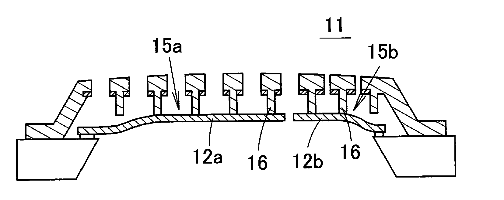
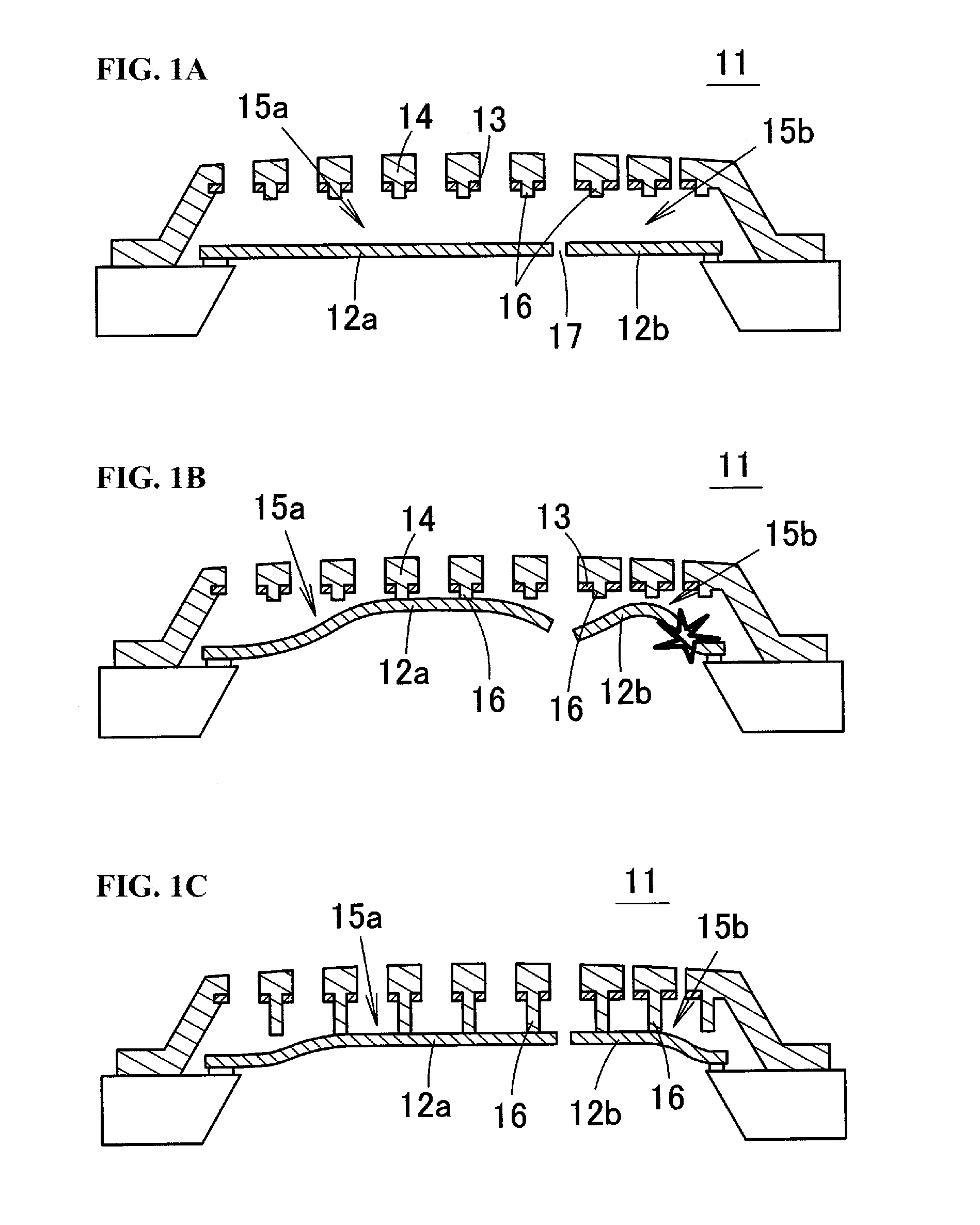
The present invention relates to a capacitance-type transducer that has multiple sensing portions and meets both the demand for higher sticking resistance and the demand for higher diaphragm damage resistance. The transducer has divided regions with different surface areas and shorter projection lengths of the stoppers, which prevents the diaphragm from easily becoming stuck and reduces the likelihood of damage. The thicker second stoppers disperse stress over the contact surface, and the increased number density of stoppers in the vicinity of the second stoppers also helps to disperse stress. The manufacturing of the stoppers is made easier, and there is no rise in manufacturing cost. Overall, the invention improves sticking resistance and damage resistance of the capacitance-type transducer.

Problems solved by technology

However, in general microphones, there is a trade-off relationship between an improvement in the acoustic vibration detection sensitivity and a reduction in the harmonic distortion rate, and it has been difficult to provide a microphone with a wide dynamic range from low-volume (low sound pressure) sounds to high-volume (high sound pressure) sounds.
If the diaphragm becomes stuck to the back plate, vibration of the diaphragm is hindered, and it becomes impossible for the acoustic sensor to detect acoustic vibration.
However, it undergoes a large amount of deformation when subjected to a high pressure load in a drop resistance test or the like as described above.
In a conventional stopper structure, there is a tradeoff relationship between the demand for higher sticking resistance and the demand for higher diaphragm damage resistance, and it has not been possible to satisfy both sticking resistance and damage resistance.

Method used


Image

  • Capacitance-type transducer
  • Capacitance-type transducer
  • Capacitance-type transducer

Examples


embodiment 1

Manufacturing Method of Embodiment 1

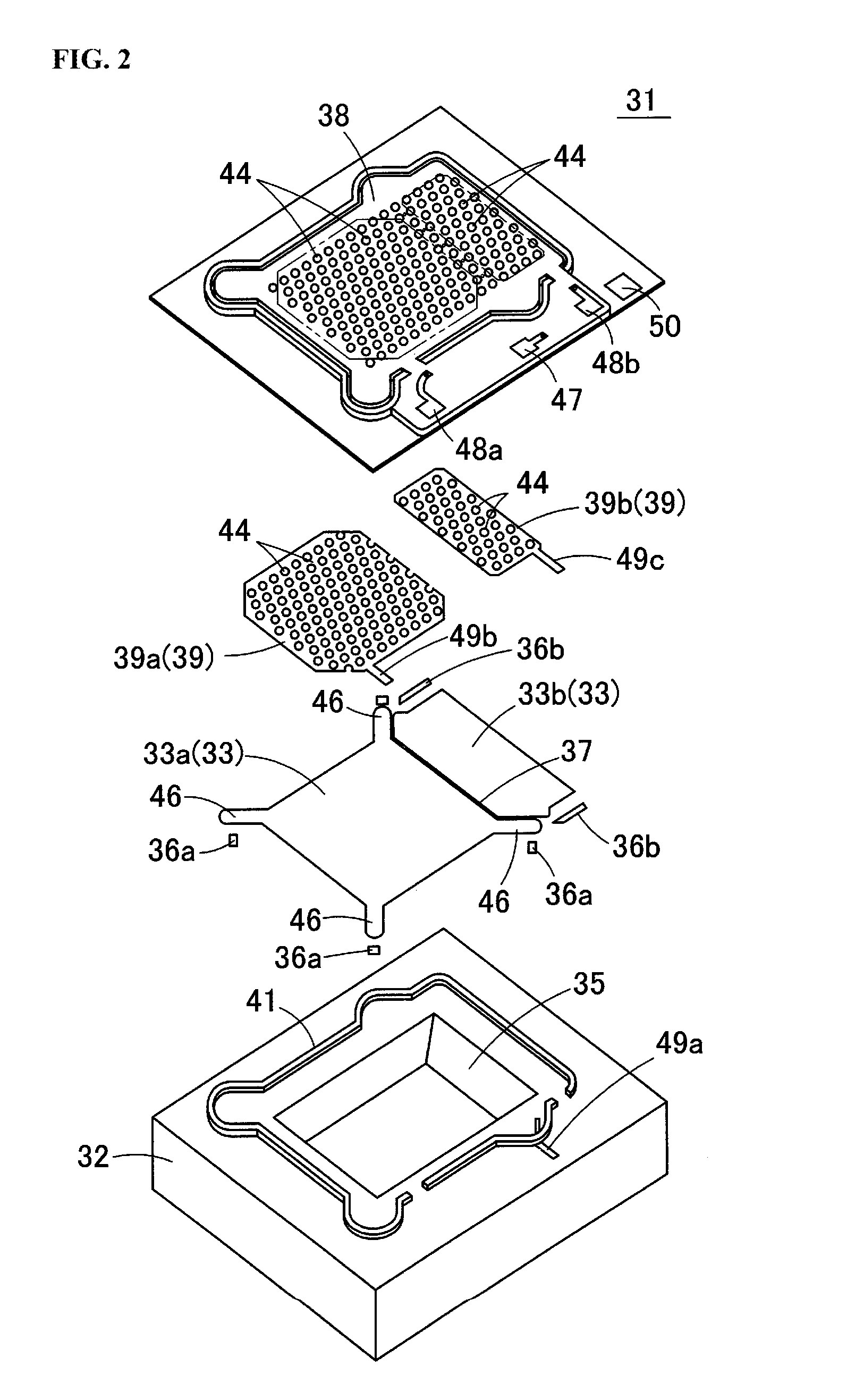
[0072]Next, a method for manufacturing the acoustic sensor 31 of Embodiment 1 will be described with reference to FIGS. 8A to 8D and FIGS. 9A to 9C. FIGS. 8A to 8D and FIGS. 9A to 9C all show enlargements of a portion of the acoustic sensor during respective manufacturing steps.

[0073]First, as shown in FIG. 8A, an oxide film 52 (SiO2) is deposited on the entirety of the upper surface of the substrate 32 (Si substrate). Next, as shown in FIG. 8B, a polysilicon film 53 is deposited on the oxide film 52, and the polysilicon film 53 is etched to form the diaphragms 33a and 33b on the upper surface of the oxide film 52. At this time, the first diaphragm 33a and the second diaphragm 33b are separated by the slit 37. Steps for forming and then removing the mask for etching will not be described here, and the same follows below.

[0074]As shown in FIG. 8C, a first sacrifice layer 54 made of a Si oxide film is deposited on the entirety of the upper surface o...

embodiment 2

[0083]FIG. 12 is a schematic cross-sectional diagram showing an acoustic sensor 71 according to Embodiment 2 of the present invention. In the acoustic sensor 71, the second acoustic sensing portion 43b is provided with stoppers 45b having a longer projection length than the stoppers 45a in the first acoustic sensing portion 43a, and more specifically, the second acoustic sensing portion 43b is provided with two types of stoppers 45b having different projection lengths, namely comparatively short stoppers 45b and comparatively long stoppers 45b. The comparatively short stoppers 45b are provided in the region that opposes the region of the second diaphragm 33b that undergoes large displacement, and the comparatively long stoppers 45b are provided in the region that opposes the region of the second diaphragm 33b that undergoes small displacement (e.g., the vicinity of the portion fixed by the anchor 36b).

[0084]FIG. 13B shows the case where stoppers 45b having a uniform length are provi...

embodiment 3

[0087]In an acoustic sensor 81 of Embodiment 3, the projection lengths of the stoppers 45a and 45b are set to change gradually. FIG. 14A is a schematic cross-sectional diagram of the acoustic sensor 81 of Embodiment 3, the cross-section being taken along line X-X in FIG. 15. FIG. 14B is a schematic cross-sectional diagram of the acoustic sensor 81 of Embodiment 3, the cross-section being taken along line Y-Y in FIG. 15. FIG. 15 shows displacement of the first diaphragm 33a and the second diaphragm 33b when pressure is applied to the two diaphragms 33a and 33b. In FIG. 15, regions with a higher dot density indicate larger displacement, and regions with a lower dot density indicate smaller displacement.

[0088]In the acoustic sensor 81 of Embodiment 3, the projection lengths of the stoppers 45a and 45b are set to change gradually such that the tips of the stoppers 45a and 45b follow the shape of the upper surfaces of the diaphragms 33a and 33b when undergoing deformation to the extent t...


PUM


Abstract

A capacitance-type transducer has a back plate having a fixed electrode, a diaphragm that opposes the back plate via an air gap and serves as a movable electrode, and at least first stoppers having a first projection length and second stoppers having a second projection length that project from at least one of a surface of the back plate on the air gap side and a surface of the diaphragm on the air gap side. At least one of the diaphragm and the fixed electrode is divided into at least a first region having a first surface area and a second region having a second surface area, a first sensing portion made up of the diaphragm and the fixed electrode is constituted in the first region, and a second sensing portion made up of the diaphragm and the fixed electrode is constituted in the second region.

Description

BACKGROUND[0001]1. Field[0002]The present invention relates to a capacitance-type transducer. Specifically, the present invention relates to a capacitance-type transducer constituted by a capacitor structure made up of movable electrodes (diaphragm) and fixed electrodes.[0003]2. Related Art[0004]In recent years, there has been demand for microphones to detect sounds with high sensitivity in a range from low sound pressure to high sound pressure. Accordingly, if the harmonic distortion rate can be reduced, it is possible to raise the maximum input sound pressure and widen the detectable sound pressure range (referred to hereinafter as the “dynamic range”) of the microphone. However, in general microphones, there is a trade-off relationship between an improvement in the acoustic vibration detection sensitivity and a reduction in the harmonic distortion rate, and it has been difficult to provide a microphone with a wide dynamic range from low-volume (low sound pressure) sounds to high-...

Claims


Application Information

Patent Timeline
Patent Type & Authority Applications(United States)
IPC IPC(8): H04R1/08H04R7/00
CPCH04R7/00H04R1/08H04R2201/003H01L2224/48091H01L2224/48137H01L2924/15151H01L2924/16152H04R19/005H01L2924/00014
Inventor OKUGAWA, AKIHIRO
Owner MMI SEMICON CO LTD
Learn More