Manufacturing process of a porous component and a porous component

Inactive Publication Date: 2015-09-24
EMBRACO IND DE COMPRESSORES E SOLUCOES EM REFRIGERACAO LTDA
View PDF8 Cites 9 Cited by
  • Summary
  • Abstract
  • Description
  • Claims
  • Application Information

AI Technical Summary

Benefits of technology

This patent describes two processes for making a porous component to be used as a flow restrictor in aerostatic bearing used on hermetic compressors. The first process involves homogenizing two different preparations of metallic powder and an organic binder, granulating them separately, and heating them up to the melting point of the binder. The resulting mixture is then filled into a mold and compressed at a certain speed and pressure until it is completely filled. The organic binder is then removed, and the material is pre-sintered at a temperature that promotes mechanical resistance. The resulting material is then controlled sintered at a temperature that promotes the formation of interconnected pores. The second process involves simultaneously homogenizing and granulating two different preparations, heating them up to the melting point of the binder, and filling the mold with the mixture. The resulting material is then pre-sintered and controlled sintered at a temperature that promotes the formation of interconnected pores. The technical effect of this patent is to provide a process for making a porous component that can be used as a flow restrictor in aerostatic bearing for hermetic compressors, with a controlled pore size and density, which can handle high temperatures and pressures.

Problems solved by technology

One of the technical challenges observed in this type of gas compressor is to ensure that the piston and cylinder have no direct contact.
A disadvantage of this type of configuration is the need of dimensional accuracy in the production of the compression rings, which makes the productive process more expensive, since the greater the dimensional accuracy, the higher the cost for manufacturing mechanical components.
Like the case of the patent previously mentioned, a disadvantage of this kind of configuration is the need of accuracy in the production of sleeves, which makes production costs more expensive.
Another disadvantage of this technique arises from the fact that this type formed with microchannels is susceptible to clogging by particles or dirtiness observed in compressor; therefore, a filter is needed to ensure that the fluid reaches the restrictors free of any kind of dirtiness, since dirtiness would prevent the equipment from properly working.
Again, production of tiny holes requires great accuracy, which may prevent the production of compressors at competitive prices at the market.
Additionally, the tiny holes may also get clogged by particles or dirtiness observed in the compressor.
Therefore, no one knows yet an efficient and satisfactory solution to offer restriction in the flow of gas used in the bearing between a piston and a cylinder of a gas compressor, with good reliability, performance, applicability and, also, of low cost.
When some material has residual pores as a consequence of its production process but the pores are not necessary to meet its engineering function, these pores are considered tolerable, when they do not harm the application, and undesirable, when they negatively affect the material's performance in the intended use or application.
These parts, when produced by other processes, need many additional operations to obtain such complexity in their shape.
On the other hand, the sintering of the components at high temperatures after their injection molding results in intense volume contraction which can lead to dimensional variations and distortions in the final part obtained.

Method used


Image

  • Manufacturing process of a porous component and a porous component
  • Manufacturing process of a porous component and a porous component

Examples


Embodiment Construction

[0025]The process for manufacturing the porous material in this invention is the powder injection molding (PIM), which is a variant technique of powder metallurgy, improved in the invention herein to make it possible to obtain a porous structure with the features necessary for the specific desired application; in other words, a porous component for the uniform distribution of gas fluid (flow restrictor) seeking aerostatic bearing.

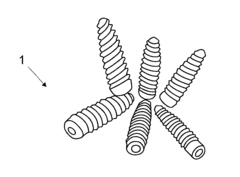
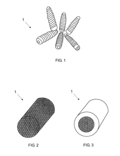
[0026]One of these applications is found in the aerostatic bearing of compressors, whose bearing is achieved through a gas layer capable of keeping a piston's linear movement in balance inside a cylinder. In order to do this, the amount of gas responsible for bearing the piston needs to be constant and, to control the fluid flow, it is necessary to use a porous component 1 with an homogenous porous structure, which not only allows for regulating the flow but also its uniform distribution in the system to be borne. The development of the porous component 1, ...


PUM

PropertyMeasurementUnit
Temperatureaaaaaaaaaa

Abstract

Manufacturing a porous component used as flow restrictor includes a metal injection molding process enhanced to obtain a component with open porosity homogeneously distributed. The flow restrictor includes at least one porous component having at least one restricting portion with some porosity dimensioned to regulate the flow of gas to an aerostatic bearing of a mechanical system, such as a hermetic compressor. Use and production of a porous component obtained by powder injection molding or powder injection molding of multi-material parts is also described, the porous component being a flow restrictor with a layer of dense material, with no open pores, on the outer surface parallel to the flow direction in which the flow through the porous component occurs, allowing it to be inserted into the bearing system without interfering with the porous structure of the core (dual porosity). Sealing existing between the porous component and its housing is described.

Description

[0001]This invention refers to an enhanced process of powder injection molding MIM in order to obtain a porous component aimed at restricting and controlling the distribution of gas fluid flow in aerostatic bearings of mechanical systems such as hermetic compressors.DESCRIPTION OF STATE OF THE ART[0002]Currently, it is very common to use piston and cylinder sets driven by electric motors for use in gas compressors of cooling equipment, such as residential, commercial and industrial refrigerators, freezers and air-conditioners. One of the technical challenges observed in this type of gas compressor is to ensure that the piston and cylinder have no direct contact. Thus, due to the relative motion between the piston and cylinder, it became necessary to bear the piston by means of a fluid, placed between the moveable surfaces of the piston-cylinder set, avoiding contact among the moveable parts and their premature wearing.[0003]Generally, for aerostatic bearings to work effectively, it ...

Claims


Application Information

Patent Timeline
IPC IPC(8): B22F3/22F16C32/06B22F3/105B22F1/103B22F1/148
CPCB22F3/225F16C32/0622B22F3/105B22F7/002B22F2998/10B22F3/1109B22F7/004C22C1/08B22F2003/1106B22F1/103B22F1/148B22F3/1021
Inventor TORRES, FERNANDO WITHERSBINDER, ROBERTOKLEIN, ALOISIO NELMOBINDER, CRISTIANOSCHROEDER, RENAN MULLERFURLAN, KALINE PAGNAN
Owner EMBRACO IND DE COMPRESSORES E SOLUCOES EM REFRIGERACAO LTDA
Why Eureka
Try Eureka