
Protector with sensor and method of molding end part of the same

a technology of end parts and sensors, applied in contact mechanisms, instruments, force/torque/work measurement apparatus, etc., can solve the problems of insufficient adhesion, inability to stably hold the wire connection parts, and inability to adjust the external shape of the resultant product, etc., to achieve excellent operability, stable holding the wire connection parts, and uneven effect of external shap

Active Publication Date: 2015-09-24
NISHIKAWA RUBBER
View PDF4 Cites 11 Cited by
  • Summary
  • Abstract
  • Description
  • Claims
  • Application Information

AI Technical Summary

Benefits of technology

The invention provides a structure for preventing degraded sensor function caused by material flow during die molding. This structure eliminates the need for an extra lid or weir on the terminal part of the extrusion molded part. Additionally, the structure prevents two wire connection parts from coming into contact with each other, which improves quality and enables inspection of wire connection parts. The primary sealing layer of the invention is colorless and transparent or colorless and semitransparent, allowing for visual confirmation of the condition of the wire connection parts.

Problems solved by technology

When water enters the wire connection parts 70, 70, connected circuits may short, which causes improper operations.
But the structure necessitates an extra process of adhesion and minutes or hours of time for curing the sealing agent.
In addition, an increase in amount of adhesive to be used has caused insufficient adhesion.
Further, use of adhesive tends to cause unevenness, which makes it difficult to stably fix the wire connection parts 70, 70.
But the structure necessitates extra members including supporting members for connecting hard-wirings, has a problem concerning heat-resistance and is degraded in mold releasability from the dies.

Method used


Image

  • Protector with sensor and method of molding end part of the same
  • Protector with sensor and method of molding end part of the same
  • Protector with sensor and method of molding end part of the same

Examples


Embodiment Construction

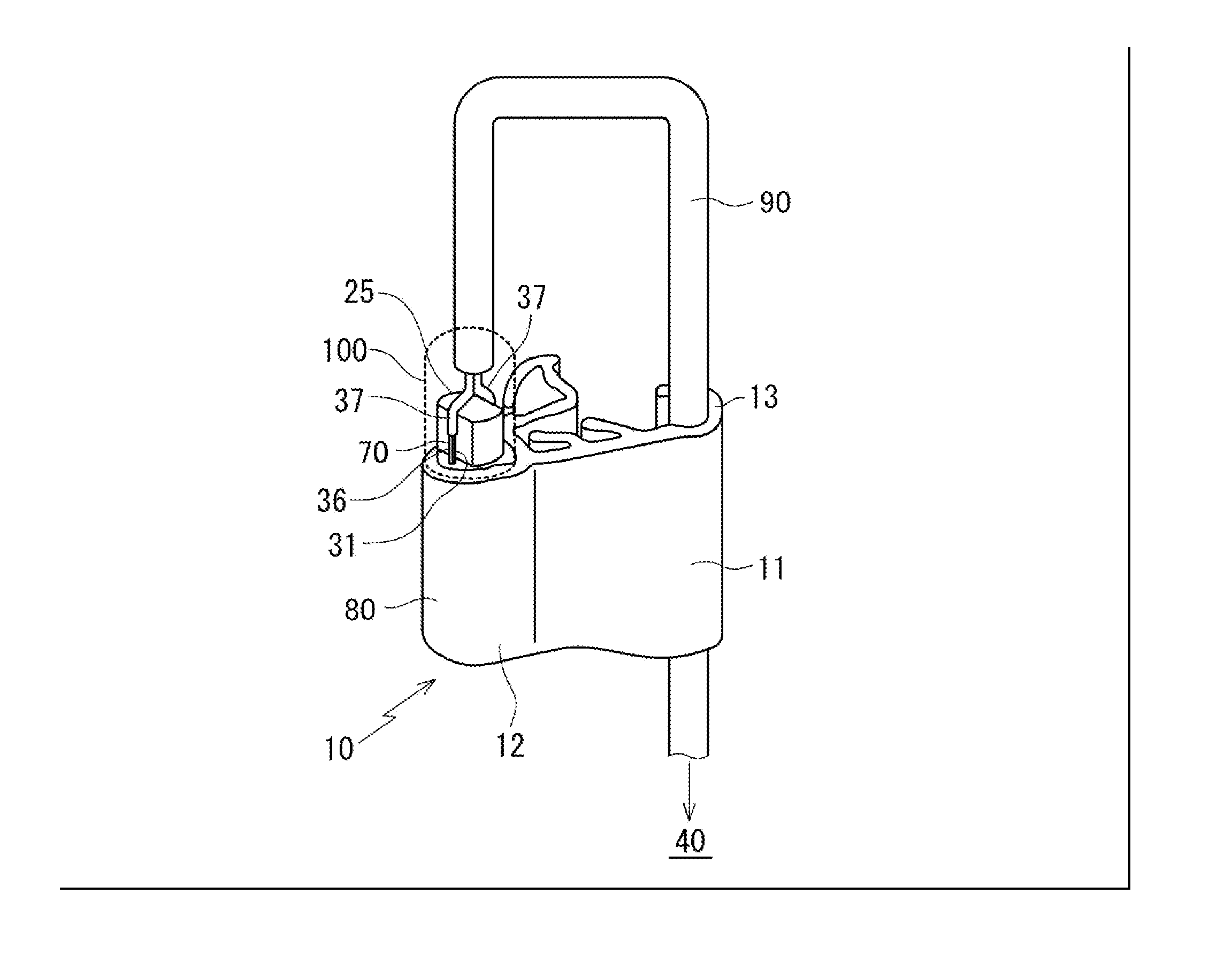
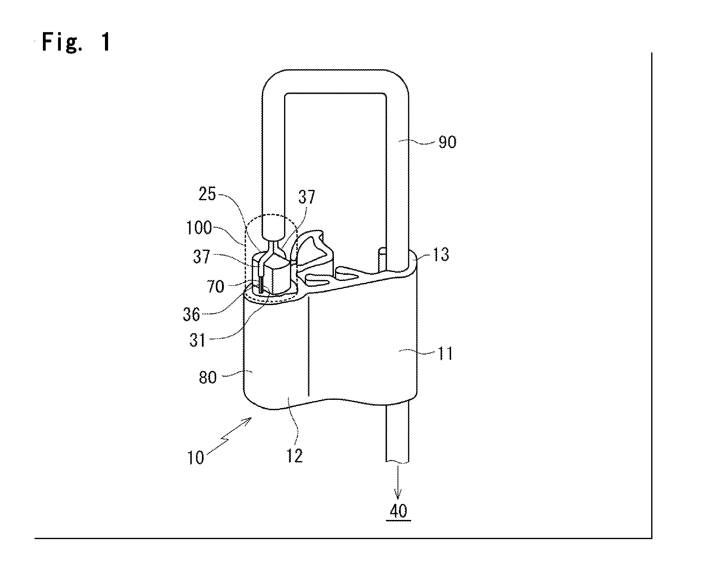
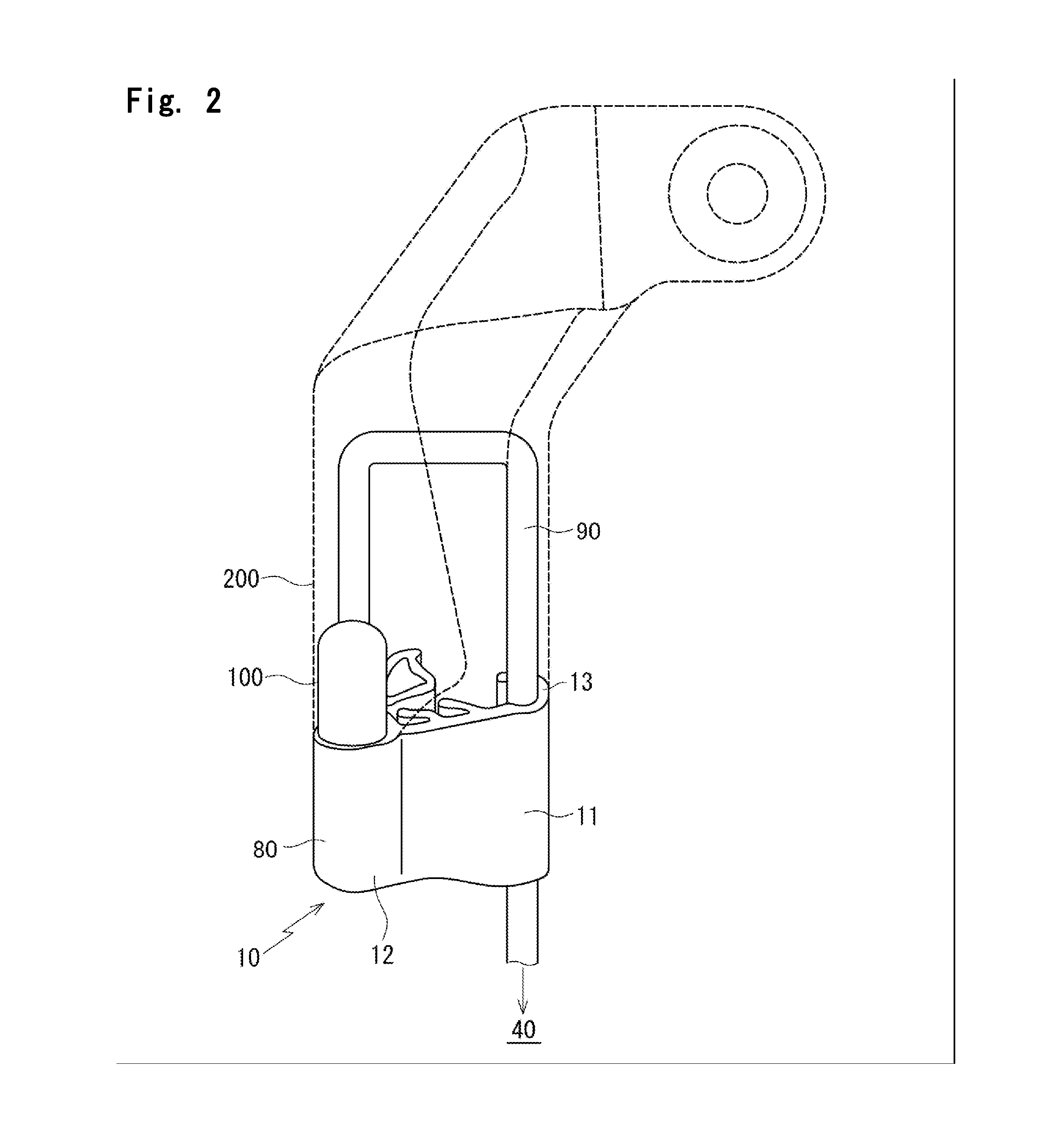
[0054]Referring to the Drawings, a protector with a sensor according to an embodiment of the present invention will be described.

[0055]A protector 10 with a sensor of the embodiment of the present invention, which extends toward a front side of an automobile body is installed on a front end surface of a sliding door 1 of an automobile shown in FIG. 5 of which the sliding door 1 moves between at least two positions to open and close an opening of the automobile body. A sensor (pressure sensitive sensor) 80 installed on the protector 10 with the sensor outputs corresponding electric signal upon detecting an object such as a part of human body (finger, hand or leg) between the sliding door 1 and a body side opening (may also be front door or side door). Both the present invention and the prior art include the structures of FIG. 7 to FIG. 10. But the present invention is different from the prior art shown in FIG. 11 in structure of a terminal part of the protector 10 with the sensor aft...


PUM


Abstract

A protector with a sensor is installed on a sliding door for detecting an object by touch between two core wires in a hollow part. In a terminal part of the protector with the sensor, the core wires drawn out are connected with leads joined with a control unit. A primary seal is formed by means of injection molding for covering wire connection parts and another end side of an insert while also covering a skin of a wire harness which ties and coats the two leads. A secondary seal is formed by means of the injection molding for coating a part formed with the primary seal and for forming an external shape of a product.

Description

CROSS REFERENCE TO RELATED APPLICATION[0001]This application claims the benefit under 35 USC §119 of JP Patent Application JP 2014-054894 filed Mar. 18, 2014, the entire disclosure of which is incorporated herein by reference.BACKGROUND INFORMATION[0002]The present invention relates to protectors with sensors and methods of molding end parts of the protectors with the sensors. When objects including fingers are disposed between openings of automobiles and opening / closing panels which move between at least two positions to open and close the openings of automobiles, the sensors of the protectors output corresponding signals for detecting the objects. The opening / closing panels include: doors such as sliding doors on wagons, station wagons or the like sliding frontward and rearward of the automobile bodies and back doors; and sun roofs.[0003]A protector 10, 20 with a sensor is installed on an automobile including a wagon shown in FIG. 5 of which a sliding door 1 (or a back door) moves...

Claims


Application Information

Patent Timeline
IPC IPC(8): E06B7/36G01D11/16G01D5/14G01D11/24B29C45/14G01L1/00
CPCE06B7/36B29C45/14065G01L1/005B29L2031/3055G01D11/24G01D11/16B29K2019/00G01D5/14H01H3/142H01H9/04E05Y2600/40E05Y2800/46E05F15/44E05F15/443B60J10/273
Inventor MATSUMOTO, MICHIHIKOHIRAKAWA, YUZO
Owner NISHIKAWA RUBBER
Learn More