Shock absorber and a method of determining the level of liquid in a shock absorber

a technology of shock absorber and liquid level, which is applied in the direction of liquid/fluent solid measurement, level indicators by physical variable measurement, engine lubrication, etc., and can solve the problems of shock absorber, inability to take inappropriate actions, and inability to draw correct conclusions

Inactive Publication Date: 2015-09-24
MESSIER DOWTY
View PDF12 Cites 12 Cited by
  • Summary
  • Abstract
  • Description
  • Claims
  • Application Information

AI Technical Summary

Benefits of technology

[0011]The communications interface may include a port in a wall of the housing, arranged to pass one or more transmission mediums through the housing wall but prevent leakage of fluid or gas in or out of the housing.
[0012]The communications interface may include an inductive loop located proximate to a wall of the cavity thereby eradicating issues associated with fluid and gas leakage through a port which may otherwise be required in the wall.

Problems solved by technology

Whilst measuring these parameters is straightforward, incorrect conclusions can be drawn and inappropriate actions can be taken if, for example, the level of hydraulic fluid within the shock absorber is estimated to be correct when in fact it is too low.
An incorrectly serviced shock absorber containing, for example, too little or too much hydraulic fluid will cause the landing gear to perform outside its design boundaries and in extreme cases could cause the shock absorber and thus the landing gear to fail.
However, optical probe systems only provide pass / fail statistic and are not capable of continuous measurement over a range of fluid levels.
However, foam and fluid contamination at the gas-liquid boundary tends to cause significant scattering and attenuation of the transmitted ultrasonic signal and piezo transducers used to generate the ultrasonic signals are fragile and thus susceptible to failure from the shock of impact of an aircraft landing gear with the ground.

Method used


Image

  • Shock absorber and a method of determining the level of liquid in a shock absorber
  • Shock absorber and a method of determining the level of liquid in a shock absorber
  • Shock absorber and a method of determining the level of liquid in a shock absorber

Examples


Embodiment Construction

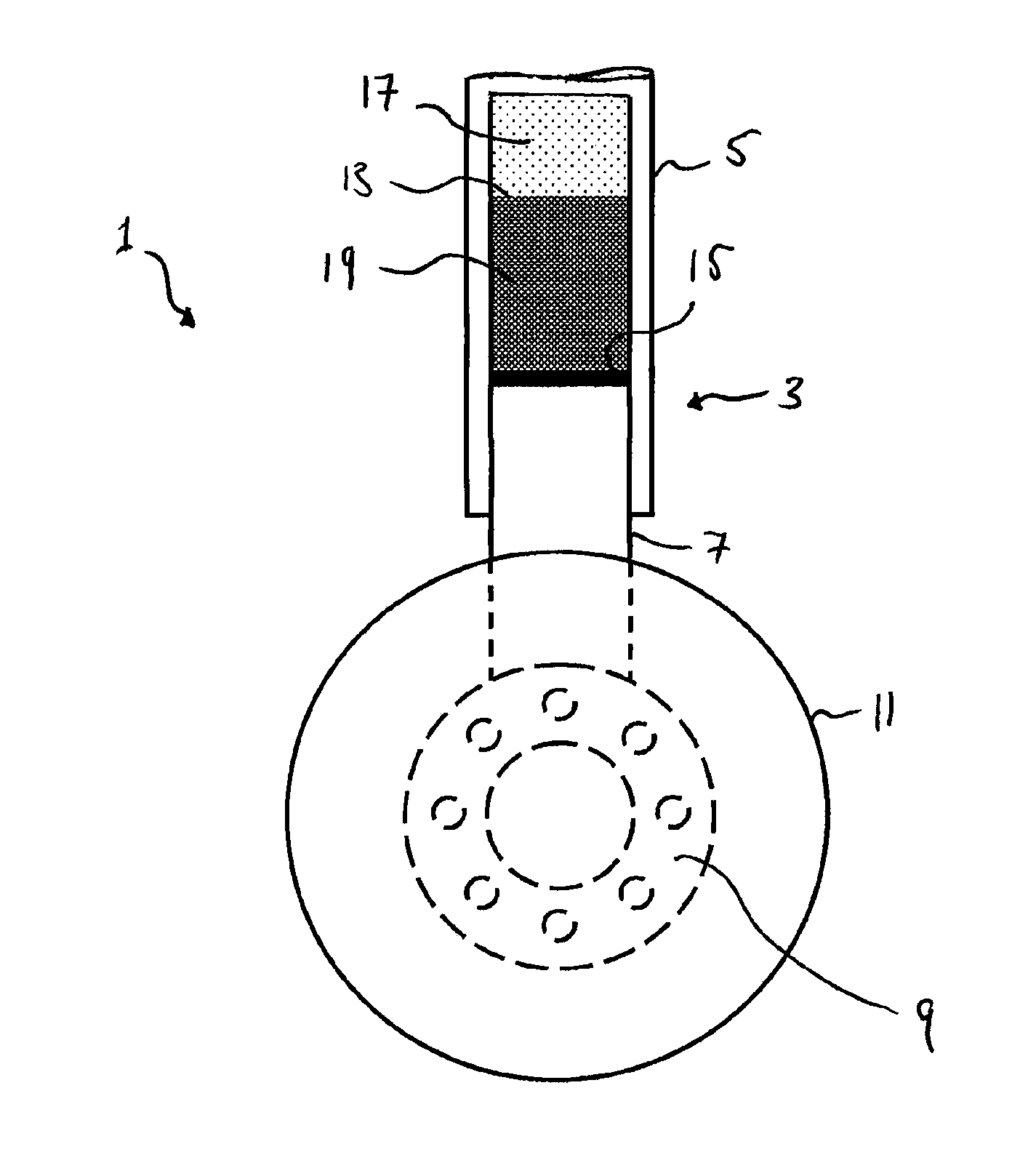
[0025]FIG. 1 shows a cross section of a known aircraft landing gear 1. The aircraft landing gear 1 comprises a telescopic support leg 3 in the form of an oleo-pneumatic shock absorber (or oleo strut) comprising a housing 5 having a bore into which a rod or piston 7 is slidably disposed. Attached to the lower end of the rod 7 is a wheel axle 9 onto which a wheel 11 may be attached. The upper end of the housing 5 (not shown) may be attached in any known manner to the airframe of an aircraft (also not shown). In other embodiments, the orientation of the shock absorber may be flipped such that a wheel is attached to the upper end of the housing 5, the lower end of the rod 7 being coupled to the airframe of an aircraft. A cavity 13, defined by the bore of the housing 5 and the upper end 15 of the rod 7, is filled with gas and a liquid - usually a hydraulic fluid such as oil. The gas and hydraulic fluid are substantially separated in normal use as designated by gas 17 and liquid 19 region...


PUM


Abstract

A telescopic shock absorber, having: a housing; a cavity located within the housing and containing a liquid and a gas; and a sensor for measuring the level of the liquid in the cavity. The sensor has: a first waveguide having a first end and a second end; and a communications interface operable to transfer electrical signals between the first waveguide to the exterior of the housing, wherein the first waveguide is arranged such that when the shock absorber is in normal use the first end is surrounded by the gas and the second end is immersed in the liquid.

Description

[0001]This application claims the benefit of European Application EP14160746.5, filed on Mar. 19, 2014, which is incorporated herein by reference in its entirety.BACKGROUND TO THE INVENTION[0002]The performance of an oleo-pneumatic shock absorber used in aircraft landing gear depends substantially on the level of hydraulic fluid situated therein. Current in-service methods for establishing the condition of an oleo-pneumatic shock absorber are based on measurement of temperature, gas pressure and shock absorber travel which are then used to estimate the level of hydraulic fluid in the shock absorber. Whilst measuring these parameters is straightforward, incorrect conclusions can be drawn and inappropriate actions can be taken if, for example, the level of hydraulic fluid within the shock absorber is estimated to be correct when in fact it is too low. An incorrectly serviced shock absorber containing, for example, too little or too much hydraulic fluid will cause the landing gear to p...

Claims


Application Information

Patent Timeline
Patent Type & Authority Applications(United States)
IPC IPC(8): G01F23/284F16F9/32
CPCF16F9/3264G01F23/284F16F9/061F16F9/32F16F9/3292B64C25/60B64F5/60
Inventor SOUTHERN, ANTHONY PAULSARTOR, PIA
Owner MESSIER DOWTY
Why Eureka
Try Eureka