CT System

a technology of cooling fluid and ct, which is applied in the field of ct system, can solve the problems of large amount of steam that may arise from overheating cooling fluid

Active Publication Date: 2015-09-24
SIEMENS HEALTHCARE GMBH
View PDF2 Cites 3 Cited by
  • Summary
  • Abstract
  • Description
  • Claims
  • Application Information

AI Technical Summary

Benefits of technology

[0006]The object of the present embodiments is to create an air-cooled CT system with a compact and constructively-simple layout.
[0010]The CT system thus has a compact and constructively-simple layout.
[0012]As an alternative, or in addition, it may be advantageous for at least one overpressure relief valve to be disposed on the cooling device.

Problems solved by technology

If, in this situation, a fracture occurs in the vacuum housing, cooling fluid reaches the hot anode and within a few seconds a large amount of steam may arise from the overheated cooling fluid.

Method used


Image

  • CT System
  • CT System
  • CT System

Examples


Embodiment Construction

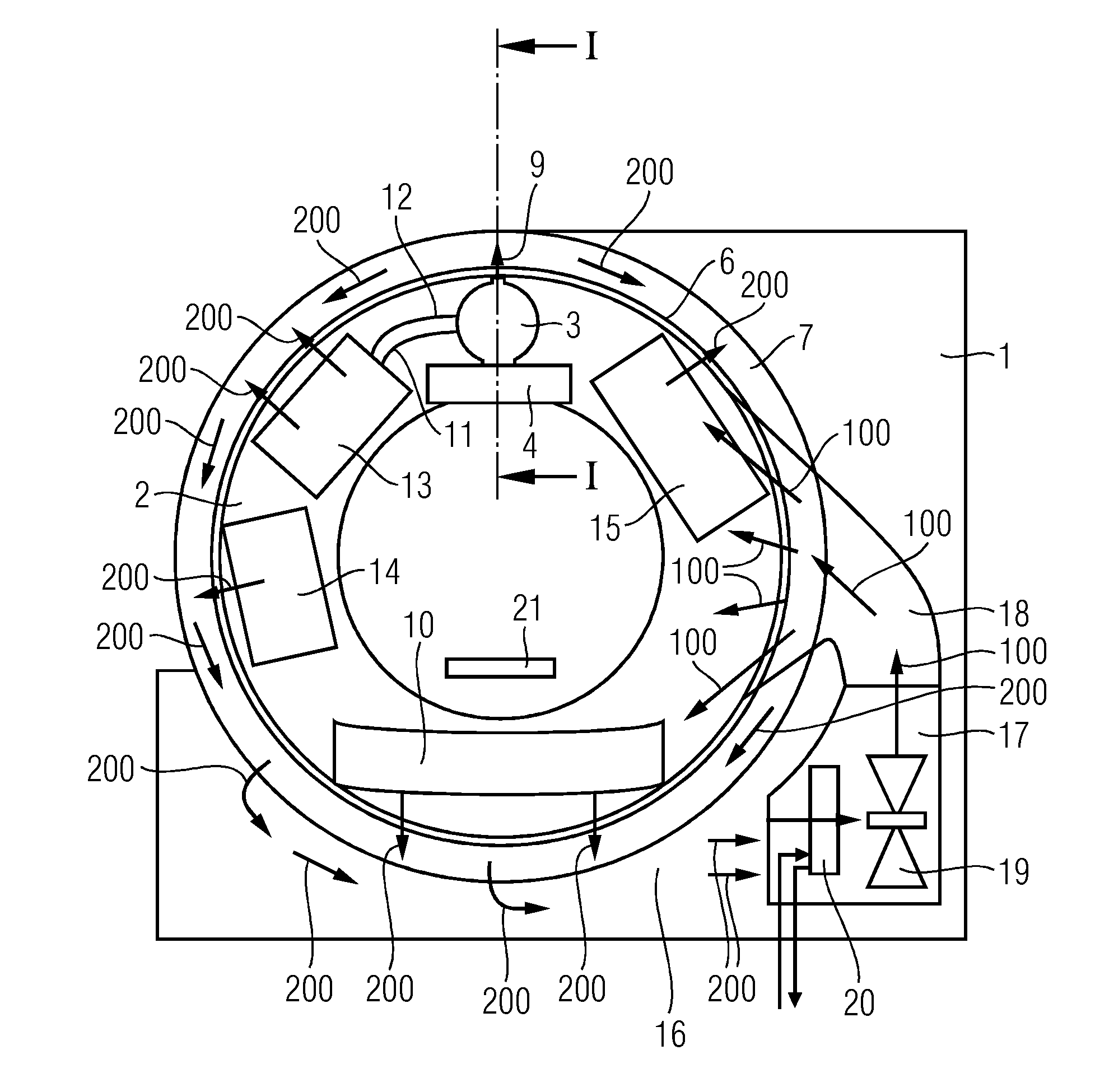
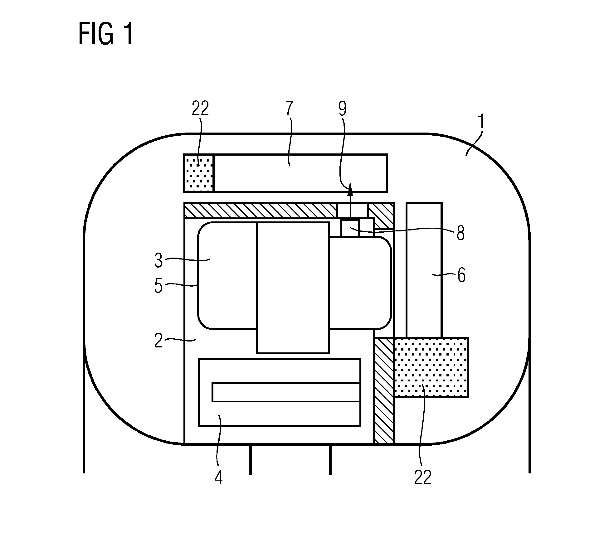
[0022]The CT (computed tomography) system depicted in FIG. 1 includes a stationary part 1 and a rotatable part 2, which is supported rotatably via a rotation bearing 22 in the stationary part 1. Disposed in the rotatable part 2 are an x-ray tube unit 3 and a collimator 4. The x-ray tube unit 3 has an x-ray tube housing 5, in which an x-ray tube is disposed, which as a result of the presentation chosen is not visible. The x-ray tube includes a vacuum housing in which a cathode and an anode are disposed. The electrons created by the cathode are accelerated in the direction of the anode and create x-ray radiation when they strike the anode. The x-ray radiation exits from the x-ray tube unit 3 and passes through the collimator 4. After the radiation leaves the collimator 4, the x-ray radiation exits from the rotatable part 2 and irradiates an examination object (e.g., patient).

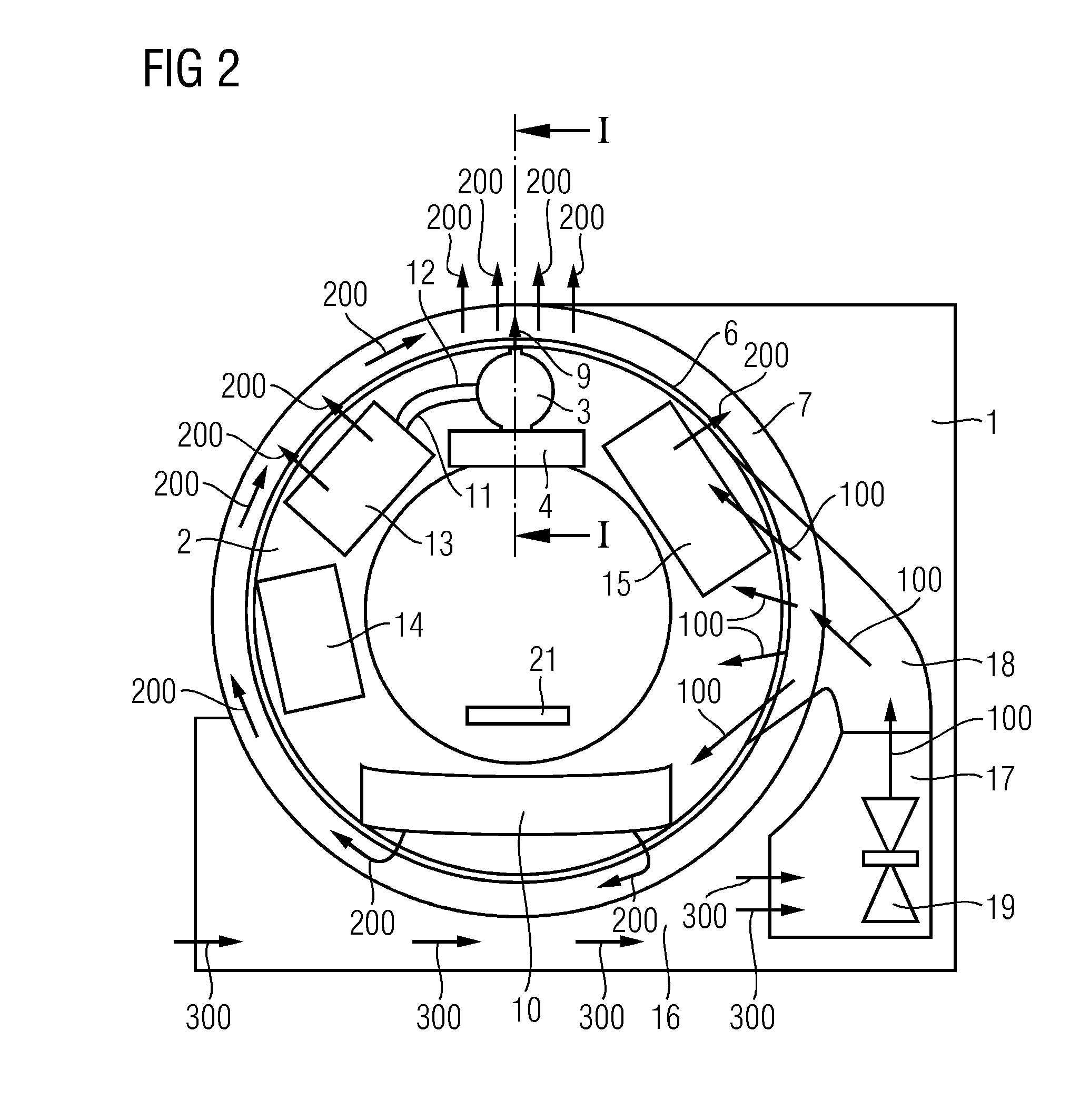
[0023]The heat occurring during the creation of the x-ray radiation within the x-ray tube is primarily taken up...


PUM

PropertyMeasurementUnit
CTaaaaaaaaaa
anti-corrosionaaaaaaaaaa
computed tomographyaaaaaaaaaa

Abstract

The embodiments relate to a CT system with a stationary part and a rotatable part, which is supported rotatably in the stationary part. At least one x-ray tube unit cooled by a cooling fluid, an x-ray detector lying opposite the x-ray tube unit, and a cooling device coupled in terms of fluid technology to the x-ray tube unit via a coolant circuit are disposed in the rotatable part. A cooling air channel, through which cooling air is able to be fed into the rotatable part, and an exhaust air channel, through which heated exhaust air is able to be taken away from the rotatable part, are disposed in the stationary part. In accordance with the embodiments, at least one overpressure relief valve is disposed in the coolant circuit, through which the cooling fluid is able to be conveyed away in the exhaust air channel.

Description

CROSS-REFERENCE TO RELATED APPLICATIONS[0001]This application claims the benefit of DE 10 2014 205 393.5, filed on Mar. 24, 2014, which is hereby incorporated by reference in its entirety.TECHNICAL FIELD[0002]The embodiments relate to a CT system.BACKGROUND[0003]A computed tomography (CT) system is described in DE 10 2005 041 538 B4. The known CT system includes a stationary part and a rotatable part that is supported rotatably in the stationary part. Disposed in the rotatable part are at least one x-ray tube unit cooled by a cooling fluid and an x-ray detector lying opposite the x-ray tube unit and also a cooling device coupled in terms of fluid technology via a cooling circuit to the x-ray tube unit. Disposed in the stationary part is a cooling air channel through which cooling air is able to be fed into the rotatable part. Furthermore, an exhaust air channel is disposed in the stationary part, through which the heated exhaust air is able to be discharged from the rotatable part.[...

Claims


Application Information

Patent Timeline
Patent Type & Authority Applications(United States)
IPC IPC(8): H01J35/10G01N23/04H01J35/06
CPCH01J35/106H01J2235/1225G01N23/046H01J35/06A61B6/032A61B6/035A61B6/4488H05G1/025
Inventor GRUCHATKA, HERBERTKUHN, ULRICHWERNER, LOTHAR
Owner SIEMENS HEALTHCARE GMBH
Why Eureka
Try Eureka