Drive unit with two coolant circuits for electric motor

a technology of coolant circuit and electric motor, which is applied in the direction of electric energy management, electric devices, gas pressure propulsion mounting, etc., can solve the problems of controllers that require cooling, complex structure, and disadvantage in cost and spa

Inactive Publication Date: 2001-11-27
AISIN AW CO LTD
View PDF11 Cites 130 Cited by
  • Summary
  • Abstract
  • Description
  • Claims
  • Application Information

AI Technical Summary

Problems solved by technology

Such structure is complicated, and is disadvantageous in terms

Method used


Image

  • Drive unit with two coolant circuits for electric motor
  • Drive unit with two coolant circuits for electric motor
  • Drive unit with two coolant circuits for electric motor

Examples


first embodiment

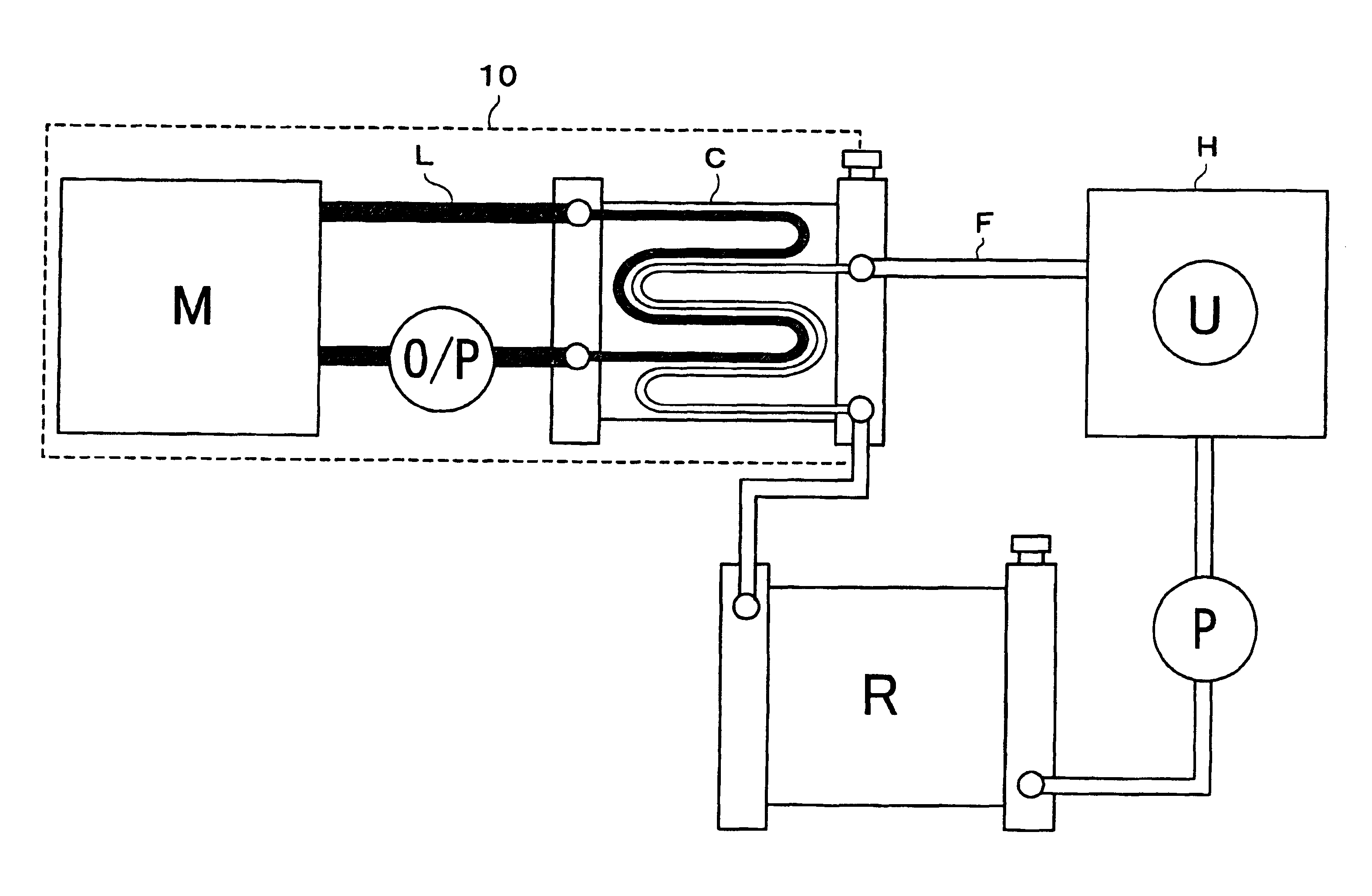
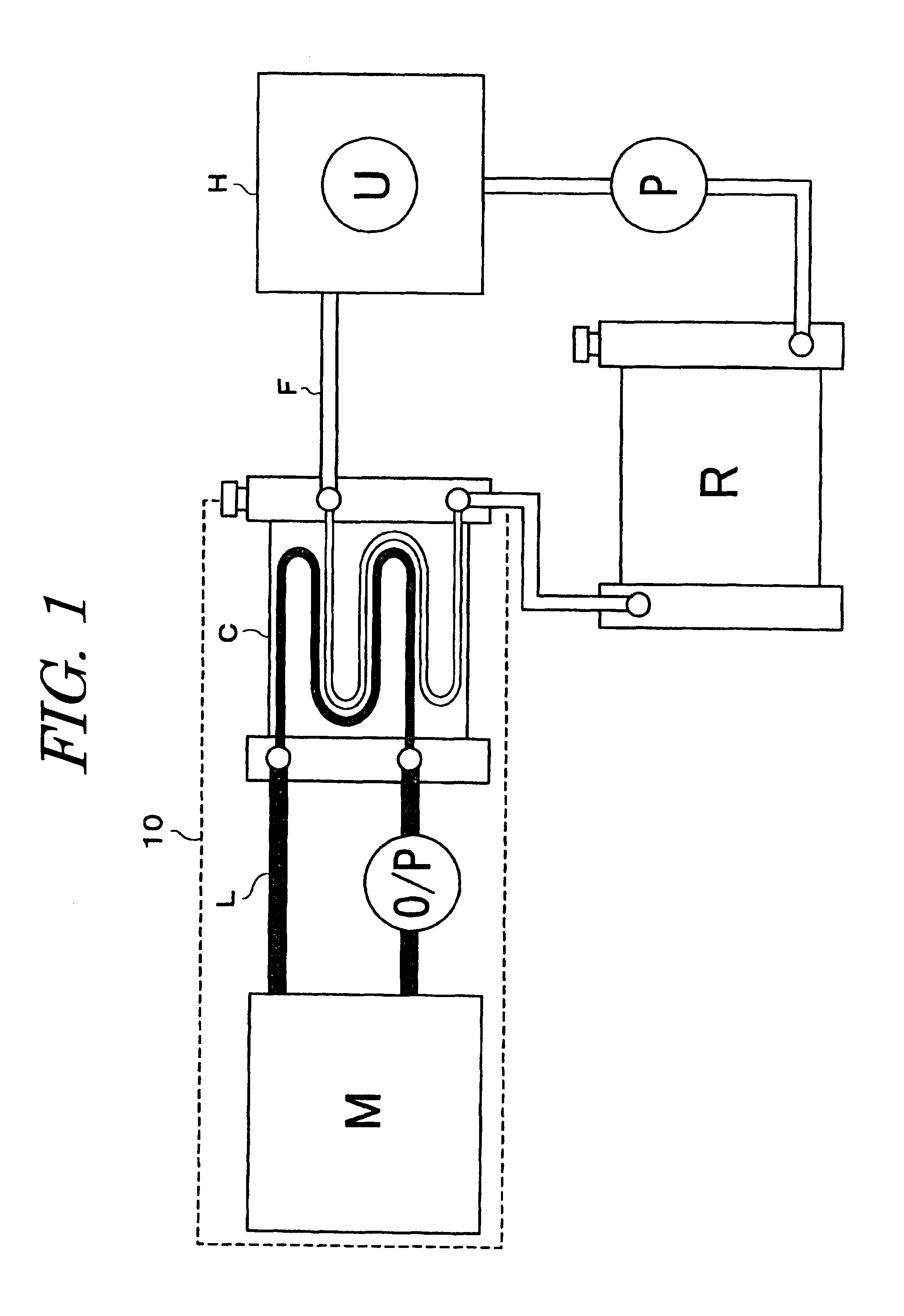
In the first embodiment, the drive unit is provided with an inverter U for controlling the motor M, and the circulation passage F is used as a cooling circuit for cooling the inverter U. For this purpose the circulation passage F (for the second coolant) includes a cooling portion H for cooling the inverter U. A radiator R is included in the cooling circuit for cooling the second coolant. The oil cooler C functioning as the heat exchanger is disposed downstream of the cooling portion H for the inverter U, in the circulation passage F. In FIG. 1, O / P denotes an oil pump, and P denotes a water pump.

As used herein, the term "inverter" means a power module comprising a switching transistor for converting the direct current from a battery power source into alternating current (three phase alternating current in the case of a three phase alternating current electric motor), accessory circuit elements, and a circuit substrate.

In the above-described drive unit, by using oils such as lubrica...

second embodiment

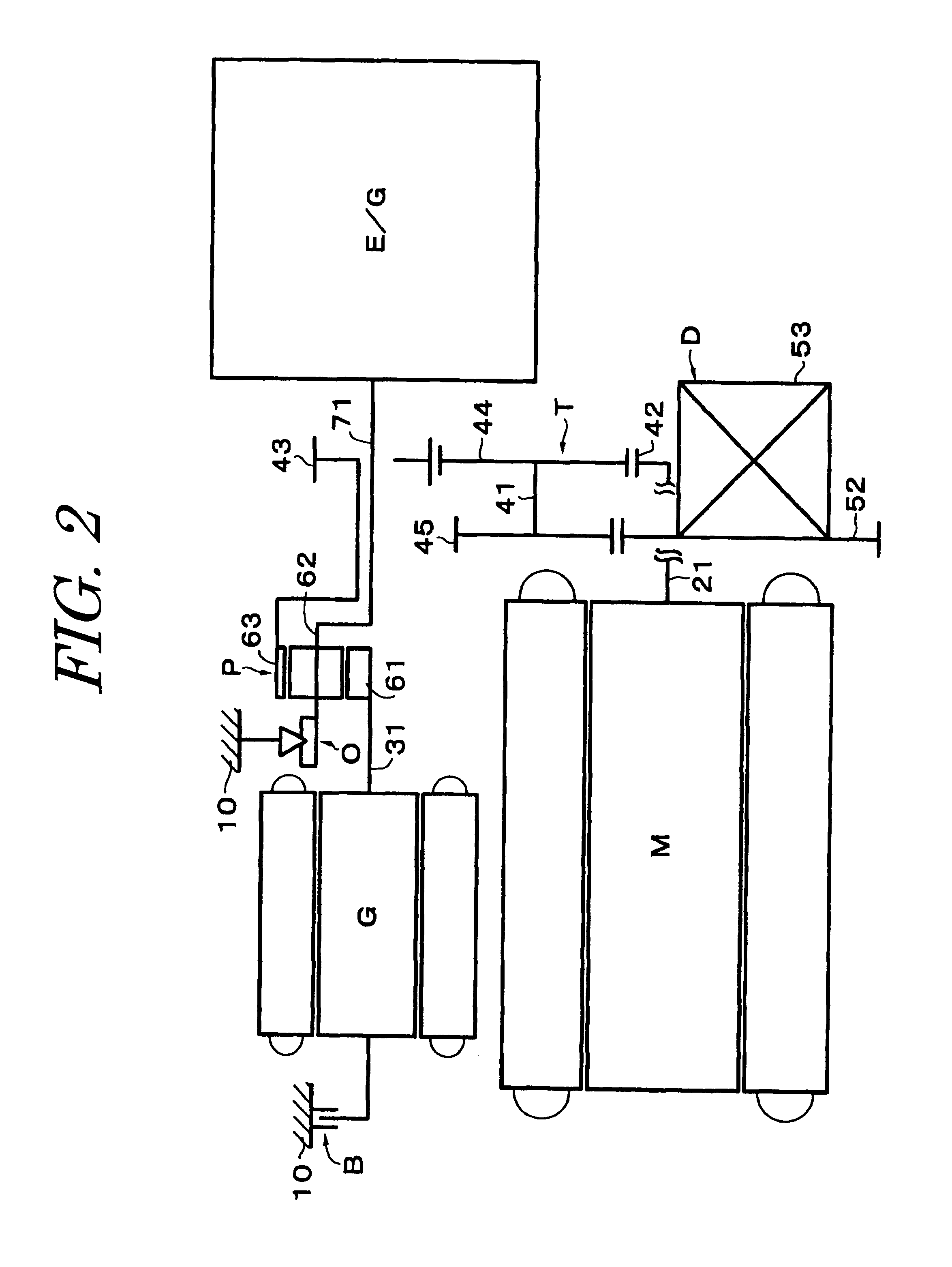
FIG. 2 shows the present invention applied to a hybrid drive unit. This unit includes, as its principal elements, an internal combustion engine (hereinafter referred to as "engine") E / G, an electric motor (hereinafter referred to as "motor") M, an electric generator (hereinafter referred to as "generator") G, and a differential D, with a planetary gear set P of a single pinion construction and a counter gear mechanism T being interposed between these elements. Furthermore, a one-way clutch O and a brake B are also provided.

As illustrated in FIG. 3, the drive unit is of a four-axis construction in which the engine E / G and the generator G are located on a first axis X.sub.1, the motor M is located on a second axis X.sub.2, the counter gear mechanism T is located on a third axis X.sub.3, and the differential D is located on a fourth axis X.sub.4, respectively. The engine E / G and the generator G are connected with the differential D through the planetary gear set P and the counter gear ...

third embodiment

With the flow configuration of the third embodiment, it is possible to pass cooling water at a lower temperature to the second chamber C.sub.4 side facing the heat transfer wall 13 of the coolant container, so that the cooling efficiency of the motor M and the generator G can be further enhanced.


PUM


Abstract

A drive unit includes an electric motor as a power source, and a simplified coolant circuit for cooling the electric motor. The drive unit further includes, in the drive unit case, a circulation passage L for coolant for cooling the motor M. A circulation passage F for a second coolant is provided separate from the circulation passage L for coolant. A heat exchange portion C within the circulation passage L for the first coolant is provided in the drive unit case for heat exchange with the second coolant in the circulation passage F, and the first coolant for cooling the electric motor is cooled by heat transfer to the second coolant in that heat exchange portion C. Accordingly, the coolant circuit in the drive unit case is simplified.

Description

1. Technical Field of the InventionThe present invention relates to a drive unit in which an electric motor is used as a power source, and more particularly, to a cooling system in a drive unit for an electric vehicle or a hybrid drive unit.2. Related ArtWhen an electric motor is used as a power source for a vehicle, the load exerted on the electric motor varies significantly with running conditions. Accordingly, in order to manage the heat generation with a heavy load, cooling is necessary. Therefore, conventionally, as disclosed in Japanese Patent Application Laid-Open No. 7-288949, the drive unit case is provided with a water passage for cooling the electric motor.However, in the conventional system, the coolant passage is formed as tubing held in a spiral groove on the outer surface of the casing, with substantially half of the circular section of the tubing exposed and extending from the outer surface of the casing. Such structure is complicated, and is disadvantageous in terms...

Claims


Application Information

Patent Timeline
IPC IPC(8): B60K6/00B60K6/04H02K9/19H02K11/04H02K16/00B60K1/00B60K1/02B60K6/20B60K6/26B60K6/405B60K6/44B60W10/26
CPCB60K6/26B60K6/405B60K6/445B60W10/26H02K9/19H02K11/0073H02K16/00B60L1/003B60L1/02B60L3/003B60L3/0061B60L11/123B60L11/14B60L15/007B60L15/20B60K1/00B60L2240/525B60K2001/003F01P2050/24F01P2050/30Y10S903/903Y10S903/906Y10S903/952Y02T10/6239B60L2210/40B60L2240/36B60L2240/421B60L2240/423B60L2240/425B60K1/02H02K11/33B60L50/61B60L50/16Y02T10/62Y02T10/64Y02T10/72Y02T10/7072Y02T10/70
Inventor HARA, TAKESHIHOTTA, YUTAKATAKENAKA, MASAYUKIAGATA, HIROMICHIYAMAGUCHI, KOZOKIDO, TAKAHIROKUTSUNA, NARUHIKO
Owner AISIN AW CO LTD
Why Eureka
Try Eureka