Catheter with multiple heating/cooling fibers employing fiber spreading features

a technology of fiber spreading and catheter, which is applied in the field of catheter, can solve the problems of time-consuming, difficult to precisely control the body temperature with ice packing, and danger of skin injury

Inactive Publication Date: 2001-10-18
WALKER BLAIR D +4
View PDF0 Cites 127 Cited by
  • Summary
  • Abstract
  • Description
  • Claims
  • Application Information

AI Technical Summary

Problems solved by technology

Although this technique has been used with some success, some physicians may find it cumbersome, and particularly time consuming.
Also, it is difficult to precisely control body temperature with ice packing.
As a result, the patient's body temperature overshoots and undershoots the optimal temperature, requiring physicians to add or remove ice.
Furthermore, there is some danger of injuring the skin, which is necessarily cooled more than any other body part.
Nonetheless, some delay is still inherent, first for a cooling element to change the temperature of the cooling medium, and then for the temperature adjusted cooling medium to cool the desired body part.
This delay is even longer if the targeted body part is an internal organ, since the most effective cooling is only applied to the skin, and takes some time to successively cool deeper and deeper layers within the body.

Method used


Image

  • Catheter with multiple heating/cooling fibers employing fiber spreading features
  • Catheter with multiple heating/cooling fibers employing fiber spreading features
  • Catheter with multiple heating/cooling fibers employing fiber spreading features

Examples


Embodiment Construction

[0113] While the foregoing disclosure shows a number of illustrative embodiments of the invention, it will be apparent to those skilled in the art that various changes and modifications can be made herein without departing from the scope of the invention as defined by the appended claims. Furthermore, although elements of the invention may be described or claimed in the singular, the plural is contemplated unless limitation to the singular is explicitly stated.

[0114] Moreover, the present invention is presently described in the context of the human body merely for ease of illustration, without any intended limitation. The invention may also be practiced with other beings, such as mammals, birds, reptiles, or other creatures. Furthermore, although the foregoing discussion has described catheter use to induce a hypothermic state, ordinarily skilled artisans (having the benefit of this disclosure) will recognize that the invention also contemplates the use of catheters to induce system...


PUM


Abstract

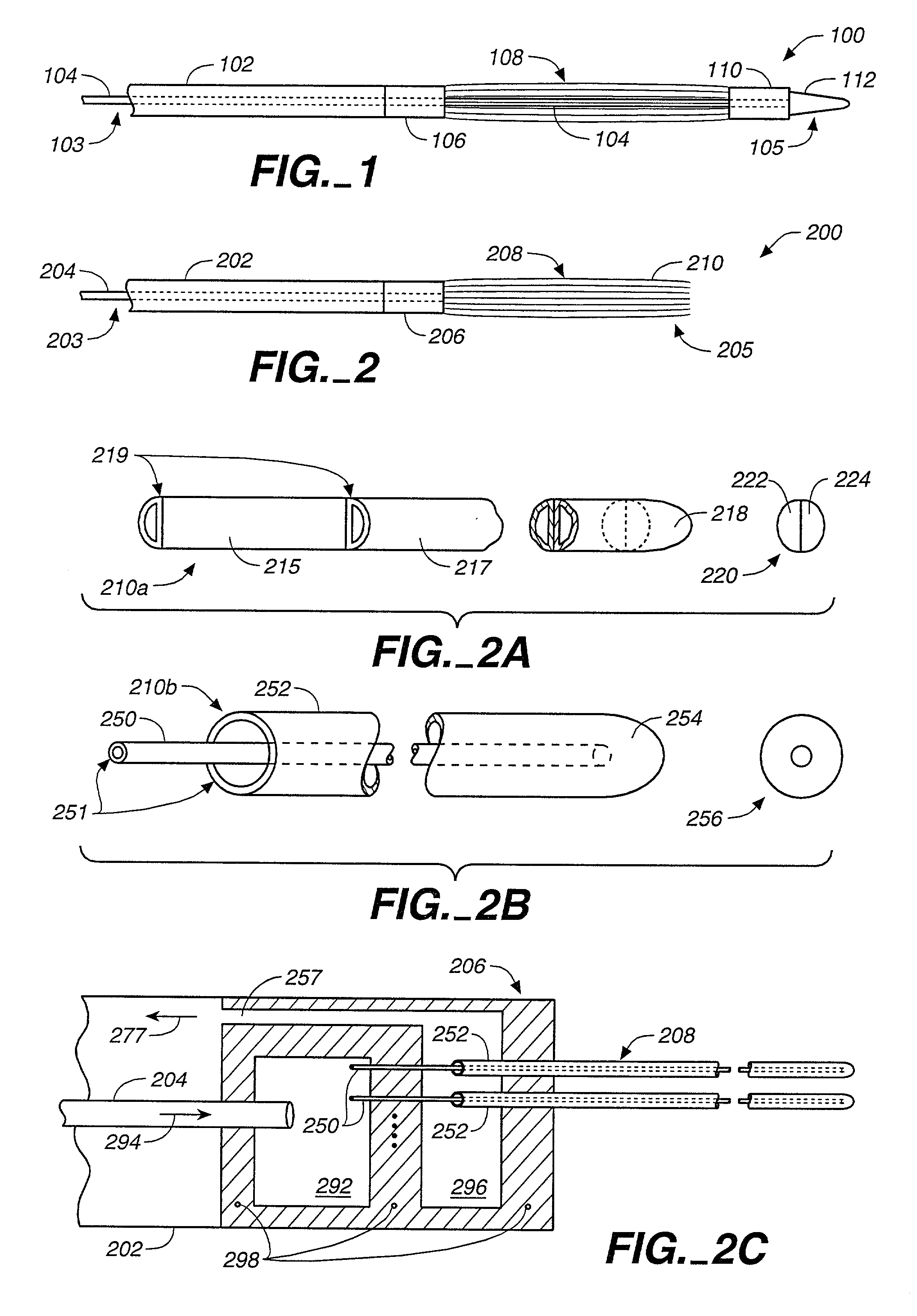
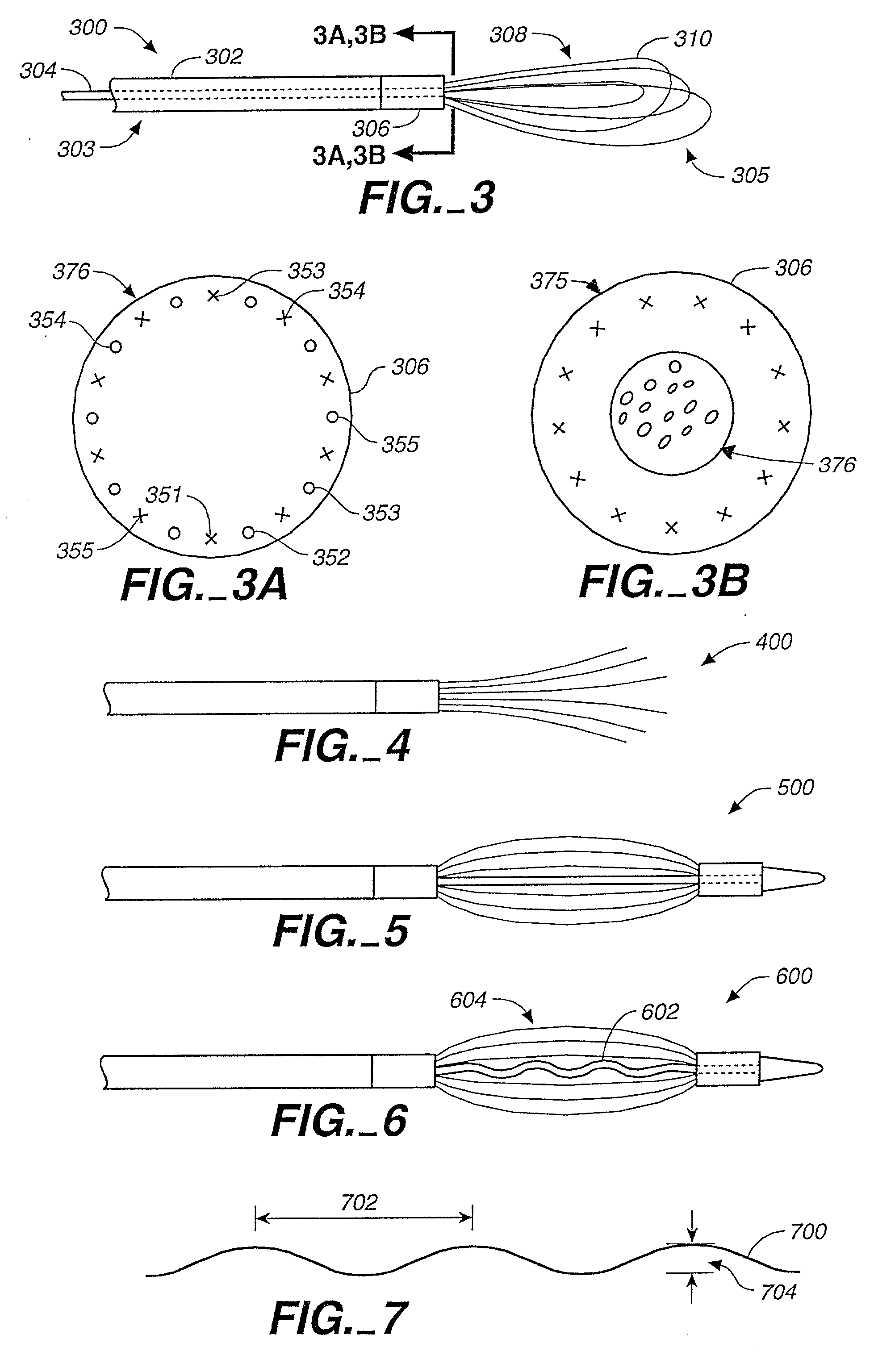
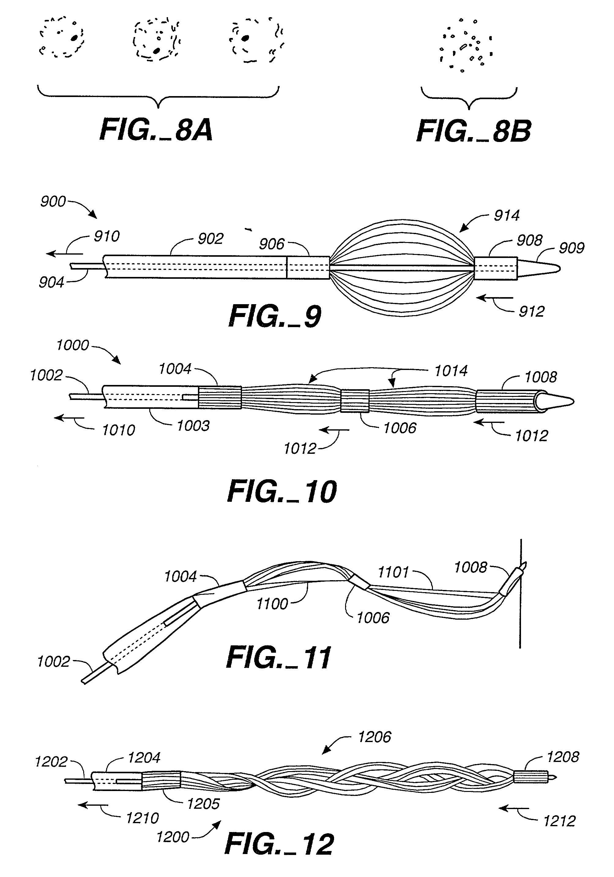
A catheter using multiple hollow fibers to carry a heating/cooling fluid employs fiber spreading features to improve heat transfer and help prevent clotting of body fluids within which the catheter is immersed. The catheter includes a length of outer tube surrounding an inner tube. The inner tube conveys fluids in one direction, and the passageway between inner and outer tubes conveys fluids in the opposite direction. The inner and outer tubes have proximal distal ends. The distal end is closed, but the proximal end is open to permit introduction of a heating or cooling fluid into the inner tube, and withdrawal of the fluid from the passageway between the inner and outer tubes. At the tubes' distal end resides a proximal fluid transfer housing coupled to multiple hollow heat exchange fibers. The distal ends of these fibers may be commonly connected to a distal fluid transfer housing and optional reservoir, which cooperatively return fluid to the passageway between inner and outer tubes. In another embodiment, each fiber includes both outflowing and return lumens, enabling the fibers' distal ends to freely move about. In another embodiment, each fiber proceeds outward from the proximal fluid transfer housing, and returns back to form a loop. In each different embodiment, the invention includes one or more actuating structures to spread the fibers. The actuating structure may include, for example, fiber shaping, a retractable spreading member, elastic bias built into the fibers, etc.

Description

[0001] This application is a continuation-in-part of U.S. application Ser. No. 09 / 133,813, entitled "Indwelling Heat Exchange Catheter and Method of Using Same," filed on Aug. 13, 1998. The foregoing application will be referred to as the parent '813 application.[0002] 1. Field of the Invention[0003] The present invention relates to catheters that effect heat exchange using a bundle of multiple hollow fibers.[0004] 2. Description of the Related Art[0005] In warm blooded creatures, temperature regulation is one of the most important functions of the body. Despite the known importance of properly maintaining body temperature, scientists have discovered certain beneficial effects of artificially inducing a hypothermic state. For instance, cooling the body can help regulate vital functions during surgery by lowering the metabolism. With stroke, trauma, and other pathological conditions, hypothermia also reduces the permeability of the blood / brain barrier. Also, induced hypothermia inhib...

Claims


Application Information

Patent Timeline
Patent Type & Authority Applications(United States)
IPC IPC(8): A61M25/00A61B18/00A61F7/00A61F7/12A61M1/36A61M5/44
CPCA61B2018/00011A61F7/12A61F7/123A61F2007/0054A61F2007/126A61M1/369A61M5/44A61M25/00A61M25/0009A61M2205/36A61M1/3623
Inventor WALKER, BLAIR D.EVANS, SCOTT M.BALDING, DAVID P.HALLAM, GREGGSHIMADA, LYNN M.
Owner WALKER BLAIR D
Why Eureka
Try Eureka