Steam producing hydrocarbon fueled power plant employing a PEM fuel cell

a technology steam generation power, which is applied in the direction of cell components, electrochemical generators, sustainable manufacturing/processing, etc., can solve the problems of increasing the overall cost of pem fuel cell inclusion in power plants, reducing the actual power output of power plants, and not operating at a temperature sufficient to cause the coolant fluid to boil and transform into steam, so as to reduce the pressure of the secondary stream and increase the steam temperature

Inactive Publication Date: 2000-09-19
INT FUEL CELLS
View PDF12 Cites 132 Cited by
  • Summary
  • Abstract
  • Description
  • Claims
  • Application Information

AI Technical Summary

Benefits of technology

Accordingly, the present invention relates to a method and apparatus for creating steam from the cooling stream of a PEM fuel cell. As the cooling stream exits the PEM fuel cell, a portion of the cooling fluid is extracted from the circulating cooling stream, thereby creating a secondary stream of cooling fluid that serves as a source of steam for the power plant. This secondary stream passes through a restriction, which decreases the pressure of the secondary stream to its boiling point. By transferring additional heat to the secondary stream, the secondary stream transforms int

Problems solved by technology

Although the phosphoric acid electrolyte fuel cell serves as a source of steam, its inclusion within a power plant increases the overall cost as compared to a PEM fuel cell because the power plant must include certain equipment and be constructed of materials capable of withstanding the operating environment, including the coolant pressure associated with a temperature range of about 375.degree. F. to about 425.degree. F.
Furthermore, de

Method used


Image

  • Steam producing hydrocarbon fueled power plant employing a PEM fuel cell
  • Steam producing hydrocarbon fueled power plant employing a PEM fuel cell
  • Steam producing hydrocarbon fueled power plant employing a PEM fuel cell

Examples


Embodiment Construction

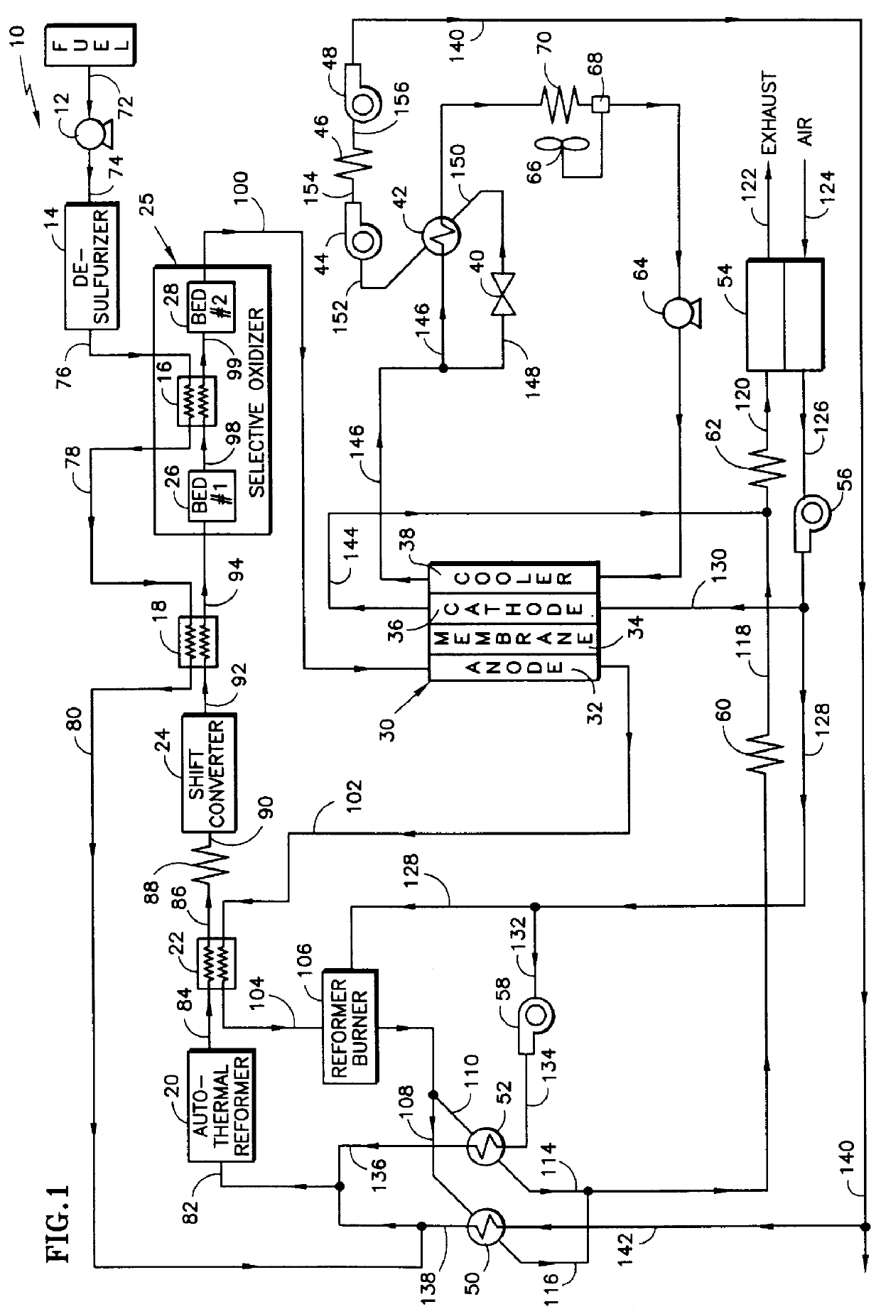
Referring to FIG. 1, there is shown a power plant 10 comprising a PEM fuel cell (hereinafter referred to as a "fuel cell") designated by the numeral 30, a means for cooling the fuel cell, a means for providing fuel reactant gas to the fuel cell, a means for providing oxidant reactant gas to the fuel cell and a means for producing steam from the cooling means. Although a power plant 10 typically consists of a plurality of fuel cells, which are collectively referred to as a cell stack assembly and connected electrically in series, for the purposes of simplicity in explaining the present invention, the block representing the fuel cell 30 illustrates only one fuel cell. Each fuel cell 30 includes a proton exchange membrane 34 disposed adjacent to and between an anode 32 and a cathode 36. As fuel reactant gas passes through the anode 32 and oxidant reactant gas passes through the cathode 36, hydrogen ions are produced that can pass through the proton exchange membrane 34 and create an el...


PUM


Abstract

The present invention relates to a method and apparatus for creating steam from the cooling stream of a proton exchange membrane (PEM) fuel cell. As the cooling stream exits the PEM fuel cell, a portion of the cooling fluid is extracted from the circulating cooling stream, thereby creating a secondary stream of cooling fluid. This secondary stream passes through a restriction, which decreases the pressure of the secondary stream to its saturation pressure, such that when the secondary stream enters a flash evaporator it transforms into steam. Creating steam from the cooling stream of a PEM fuel cell power plant provides the fuel processor with a co-generated source of steam without adding a significant amount of auxiliary equipment to the power plant.

Description

This invention relates to a fuel cell power plant and more particularly to a power plant employing a proton exchange membrane fuel cell.Many industrial facilities utilize fuel cell power plants to satisfy both their daily and temporary need for electricity. The fuel cell itself consists of an anode, a cathode and an electrolyte that separates the two. Fuel reactant gas, which is typically a hydrogen rich stream, enters the anode of the fuel cell and oxidant reactant gas, which is commonly air, enters the cathode of the fuel cell. A catalyst in the anode causes the hydrogen to oxidize resulting in the creation of hydrogen ions, which pass through the electrolyte to the cathode, thereby creating an electric potential across the fuel cell.There are various types of fuel cells, which vary according to their electrolyte. The electrolyte is the ionic conducting substance between the anode and the cathode. One type of fuel cell includes an acid electrolyte, such as phosphoric acid (H.sub.3...

Claims


Application Information

Patent Timeline
IPC IPC(8): H01M8/06H01M8/04
CPCC01B3/382C01B3/384C01B3/48H01M8/0612C01B2203/0233C01B2203/0244C01B2203/0283C01B2203/044C01B2203/047C01B2203/066C01B2203/0816C01B2203/0822C01B2203/0827C01B2203/0883C01B2203/1258H01M8/04029H01M8/04119H01M2300/0082Y02E60/50Y02P20/10
Inventor VAN DINE, LESLIE L.BONVILLE, LEONARD J.
Owner INT FUEL CELLS
Why Eureka
Try Eureka