
Eureka
For R&D, Eureka makes reading and utilizing patents & technical documents easy.
Eureka AIR
Designed for self-driven R&D workflows. Generate viable solutions, solve complex R&D challenges, empower your innovation with AI.

Eureka Materials
Designed for material experts only. Revolutionize your material R&D, from search, analyze, to developing new materials.

TechResearch
Generate reliable direction feasibility study reports for your R&D in just a few steps.

TechSeek
Discover and master advanced knowledge NOW. Basics, ideas, possibilities, all at once.

TechMind
As an expert in R&D Theories, TechMind can generates customized viable solutions instantly.

TechRisk
Analyze your overall solution with one click, know your potential R&D risks in advance.

TechMonitor
Get weekly tech updates, stay abreast of the latest tech innovations and key insights.
Nonaqueous secondary battery and battery control system
- Summary
- Abstract
- Description
- Claims
- Application Information
AI Technical Summary
Benefits of technology
Problems solved by technology
Method used
Image

Examples
example 1
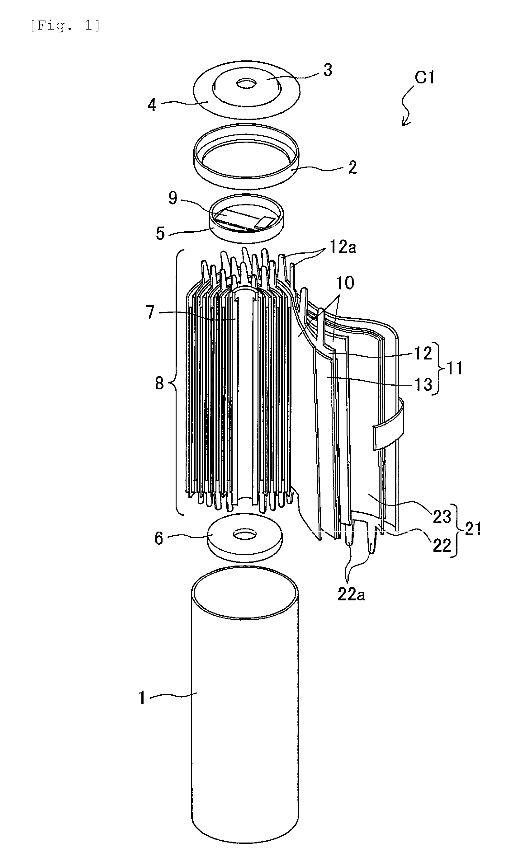
[0029]FIG. 1 is an exploded perspective view illustrating a configuration of the lithium ion secondary battery of this example in a partial cross-sectional view.
[0030]A lithium ion secondary battery C1, for example, is a winding type cylindrical lithium ion secondary battery which is mounted in a hybrid automobile, an electric automobile, and the like, and as illustrated in FIG. 1, has a configuration in which a winding type electrode group 8 is contained in a bottomed cylindrical battery can 1 having conductivity.
[0031]The electrode group 8 is configured by superposing a strip-like positive electrode 11 and a negative electrode 21 in the shape of a layer through a porous separator 10 having insulating properties, by being wound around an axial core 7 of a resin, and by fixing an outermost separator 10 thereon using tape.
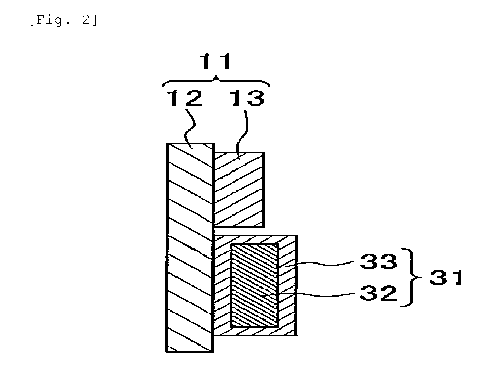
[0032]The positive electrode 11 includes a positive electrode foil 12 formed of aluminum foil, and a positive electrode mixture layer 13 coated on both surfaces of ...
example 2
[0052]Next, Example 2 will be described with reference to FIG. 5.
[0053]FIG. 5 is a cross-sectional view schematically illustrating the configuration of a positive electrode and an ion supply unit of this example. Furthermore, the same reference numerals are applied to the same constituent elements as those in Example 1, and thus the detailed description thereof will be omitted.
[0054]In a characteristic configuration of this example, an undissolved conductive portion 34 is disposed in a portion interposed between the ion supply unit 31 and the positive electrode foil 12, and thus electrical connection between the ion supply unit 31 and the positive electrode foil 12 is stably ensured. The covering portion 33 partially covers the ion supply source 32, maintains the ion supply source 32 and the electrolytic solution in a non-contact state, and is dissolved at a reaction potential. The covering portion 33 covers an exposed portion of the outer surface of the ion supply source 32 which r...
example 3
[0067]Next, Example 3 will be described with reference to FIG. 8.
[0068]This example is identical to Example 1 except for the configuration of the ion supply unit.
[0069]FIG. 8 is a cross-sectional view schematically illustrating a configuration of a positive electrode and an ion supply unit of this example. Furthermore, the same reference numerals are applied to the same constituent elements as those in Example 1, and thus the detailed description thereof will be omitted.
[0070]In a characteristic configuration of this example, an electrolytic covering portion (a first covering portion) 36 which is disposed between the ion supply source 32 and the positive electrode foil 12 and sets the ion supply source 32 and the positive electrode foil 12 in an electrically disconnected state, and is electrolyzed and disappears at the time of overcharge is disposed. The covering portion 36 was formed by mixing lithium carbonate with polyvinylidene fluoride (PVDF) which is a positive electrode bindi...
PUM
 Abstract
Description
Claims
Application Information
 - R&D Engineer
- R&D Manager
- IP Professional
- Industry Leading Data Capabilities
- Powerful AI technology
- Patent DNA Extraction
Browse by: Latest US Patents, China's latest patents, Technical Efficacy Thesaurus, Application Domain, Technology Topic, Popular Technical Reports.
© 2024 PatSnap. All rights reserved.Legal|Privacy policy|Modern Slavery Act Transparency Statement|Sitemap|About US| Contact US: help@patsnap.com