Method for manufacturing multi-core optical fiber

a manufacturing method and multi-core technology, applied in the direction of manufacturing tools, material analysis using wave/particle radiation, instruments, etc., can solve the problems of inability to manufacture mcf by using the rid method, inability to achieve satisfactory core position accuracy, and inability to achieve mass productivity, etc., to achieve satisfactory economic efficiency and productivity, reduce the diameter of the dummy pipe, and reduce the effect of transmission loss

Inactive Publication Date: 2015-10-01
SUMITOMO ELECTRIC IND LTD
View PDF13 Cites 6 Cited by
  • Summary
  • Abstract
  • Description
  • Claims
  • Application Information

AI Technical Summary

Benefits of technology

[0014]On the other hand, when the MCF is manufactured by use of the RID method, there are the positions of the holes in the cladding material except for the center on the axis and, therefore, when the diameter of the spliced dummy pipe is reduced in part, the core rods on the peripheral side can be brought into a butt against the diameter-reduced part of the dummy pipe but the core rod on the center side cannot be brought into a butt against it. A long process time is needed for reducing the diameter of the dummy pipe to one enough to bring the core rod on the center side into a butt against it. Since the thickness of the dummy pipe becomes smaller relative to the outer diameter in the case of MCF, as described previously, the dummy pipe is likely to become noncircular in the diameter reduction process and it is thus difficult to control the outer diameter; therefore, it was difficult to perform the diameter reduction process to a predetermined outer diameter, per se. For this reason, it was difficult to secure the flow path of gas while fixing the cores at predetermined positions so as to prevent them from dropping, or, it was necessary to use a core fixing member to secure the flow path of gas while preventing the cores from dropping. For the above reasons, the manufacturing method of the MCF by use of the RID method had the problems that it was difficult to perform the purifying process in vapor phase between the inner walls of the holes of the cladding material and the outer peripheries of the core rods and that it was difficult to obtain the optical fiber with a low transmission loss, free of impurities at the interfaces between the core rods and the holes in the cladding material, while achieving satisfactory economic efficiency and productivity together.
[0015]The present invention has been accomplished in order to solve the above problems and it is an object of the present invention to provide a method for manufacturing an MCF (multi-core optical fiber) with excellent economic efficiency and productivity and with a low transmission loss.

Problems solved by technology

It was believed on the other hand that, in producing a Multi-Core optical Fiber (hereinafter referred to as “MCF”) by use of the RID method, since the core insertion holes were not collapsed at the preform stage and there were the holes other than that at the center of the cladding material, each core was not always brought closer to the center of each hole and it was disadvantageous in achieving higher accuracy of core arrangement in a cross section.
For this reason, it was difficult to manufacture the MCF by use of the RID method.
Particularly, there is no known method capable of manufacturing the MCF while achieving satisfactory core position accuracy, transmission loss, and mass productivity all together by use of the RID method; for this reason, in the conventional manufacture of MCF, the core arrangement positions were once fixed at the preform stage for MCF by the Rod-In Collapse method (hereinafter referred to as “RIC method”), the core positions were corrected by periphery grinding or the like if needed, and, thereafter, the pipe was drawn by ordinary fiber drawing to obtain optical fiber.
The need for higher accuracy of core arrangement positions is a particular problem to the MCF and an increase in splice loss will occur unless the core positions are accurately arranged where all the cores are optically connected in a lump, in optically splicing two MCFs or in optically splicing the MCF to a light receiving device or to a light emitting device.
The thinning of the dummy pipe leads to a decrease in strength of the spliced part.
On the other hand, if the area of the spliced part is increased, the area of the cladding portion will increase by that degree, resulting in unwanted increase of the fiber diameter of MCF.
As described above, the method of manufacturing the MCF by use of the RID method had the problems of the limitation to decrease of thickness of the dummy pipe, degradation of core position accuracy, and increase in transmission loss due to residual OH groups, when compared to the SCF case.

Method used


Image

  • Method for manufacturing multi-core optical fiber
  • Method for manufacturing multi-core optical fiber
  • Method for manufacturing multi-core optical fiber

Examples


Embodiment Construction

Description of Aspects of Embodiment of Invention

[0023]Aspects of the embodiment of the invention will be first described as enumerated below.

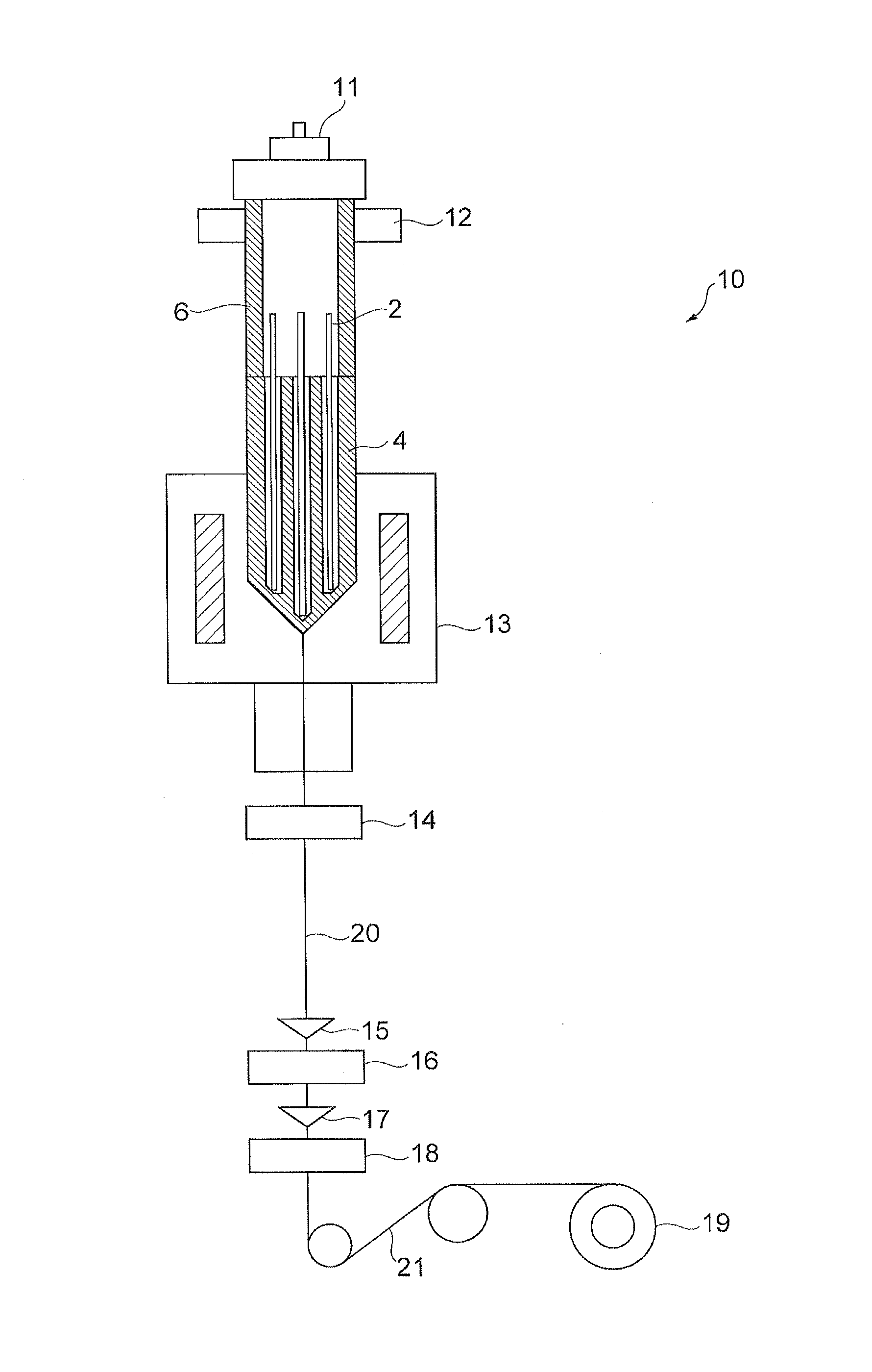
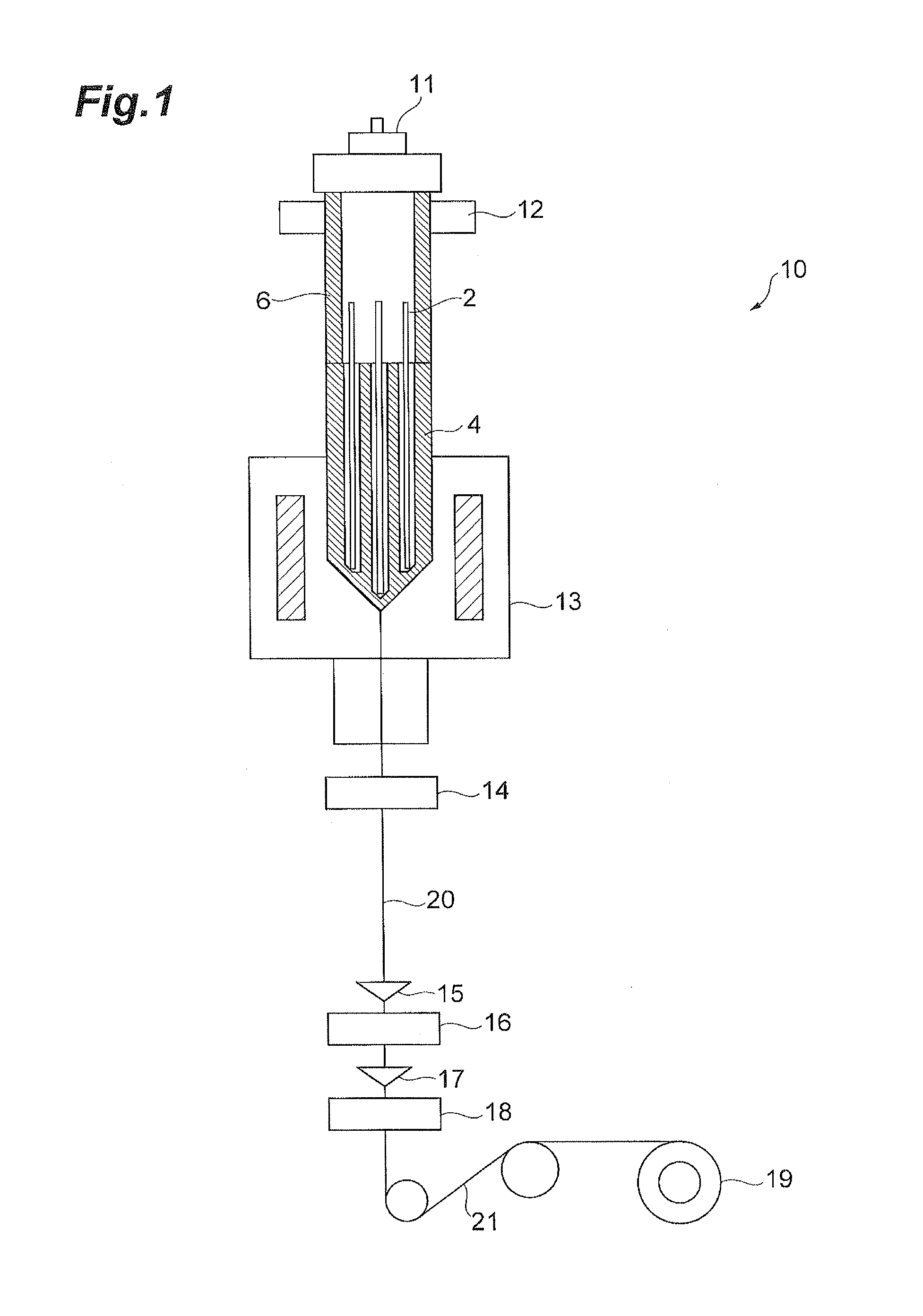
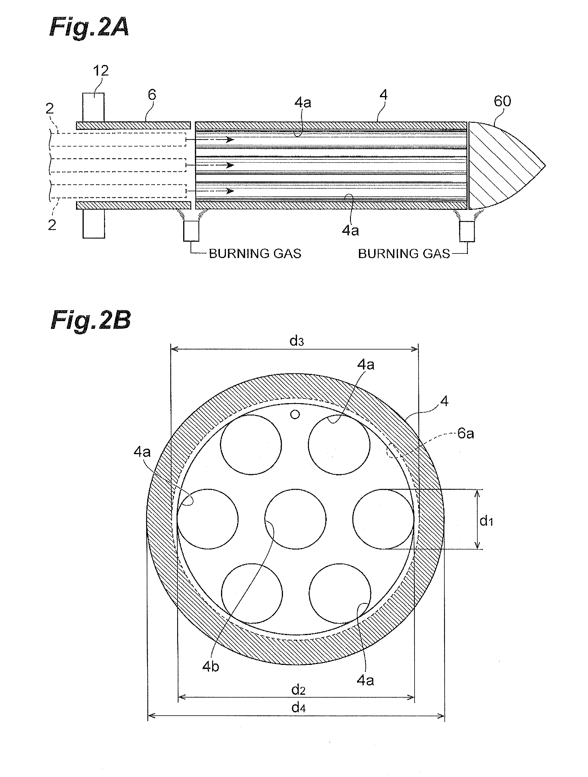
[0024](1) A method for manufacturing an MCF (multi-core optical fiber) according to a first aspect of the embodiment of the invention is a method comprising: a cladding material preparing step of preparing a cladding material comprised of silica-based glass and having an average concentration JOH of OH groups less than a predetermined concentration; a core rod producing step of producing a plurality of core rods comprised of silica-based glass and each having a core portion and a part of a cladding; a hole making step of making a plurality of holes in the cladding material so as to extend along an axial direction thereof; a splicing step of splicing a dummy pipe to a first end side of the cladding material; an inserting step subsequent to the splicing step, the inserting step being a step of inserting the plurality of core rods into the respec...


PUM

PropertyMeasurementUnit
diameteraaaaaaaaaa
diameteraaaaaaaaaa
roughnessaaaaaaaaaa

Abstract

A manufacturing method according to an embodiment of the invention includes a step of calculating Pj0.1 satisfying (62.6×JOH+1175)×Pj=0.1, where Pj is an optical power ratio at the wavelength 1383 nm of a portion corresponding to a cladding material of an MCF after drawn, and an outer diameter ratio Pcc0.1 of core portions to core rods to obtain Pj0.1. The core rods have an outer diameter 2R0.1 satisfying the condition that a ratio Pcc is not less than the ratio Pcc0.1, and the cladding material has holes formed in a diameter larger by C (not less than 0.15 mm and not more than 1.5 mm) than the outer diameter of the core rods.

Description

BACKGROUND OF THE INVENTION[0001]1. Field of the Invention[0002]The present invention relates to a method for manufacturing a multi-core optical fiber.[0003]2. Related Background Art[0004]Japanese Patent No. 5176274 (Patent Literature 1) discloses a Rod-In Drawing method (hereinafter referred to as “RID method”) for producing a Single Core Fiber (hereinafter referred to as “SCF”) by drawing. In this RID method, the SCF is produced by inserting a core into a pipe of a cladding material having a hole at a center only and arranging this cladding material in the vertical direction. Then, the pipe is guided into a drawing furnace and drawn into fiber while heated to integrate. This RID method has a step of removing water for the core rod and the interior surface of the cladding pipe, after the insertion of the core into the cladding pipe; a step of sealing at least one end of the cladding pipe; and a step of drawing the pipe from one end into optical fiber while connecting the gap betwee...

Claims


Application Information

Patent Timeline
Patent Type & Authority Applications(United States)
IPC IPC(8): C03B37/012G02B6/255C03B37/025G02B6/02
CPCC03B37/01222G02B6/02042C03B2203/34C03B37/025C03B37/0253G02B6/255C03B37/01231C03B37/02736C03B37/02754C03B2201/04C03B2201/075C03B2201/12C03B2201/20C03B2205/12
Inventor NAKANISHI, TETSUYASASAKI, TAKASHI
Owner SUMITOMO ELECTRIC IND LTD
Why Eureka
Try Eureka