Method for Operating an Internal Combustion Engine, and Internal Combustion Engine

Active Publication Date: 2015-10-01
DAIMLER TRUCK AG
View PDF1 Cites 20 Cited by
  • Summary
  • Abstract
  • Description
  • Claims
  • Application Information

AI Technical Summary

Benefits of technology

[0032]This is based on the finding that fuel enrichment of the exhaust gas with uncombusted and/or partially combusted fuel may result in undesirable so-called sooting of the feed air tract when this exhaust gas is recirculated. This is avoided in the present case, since enrichment of exhaust gas is carried out only for the cylinder/cylinders whose exhaust gas is not able, or at best is able only to a negligible extent, to pass into an exhaust gas recirculation line via which exhaust gas is recirculatable into the feed air tract of the internal combustion engine. Functionally reliable operation of the internal combustion engine may be ensured in a particularly simple manner due to the avoidance of uncombusted fuel a

Problems solved by technology

The formation of NO2 at the oxidation catalytic converter is improved by high proportions of noble metals, for example platinum and platinum group metals, which entails corresponding costs and is therefore disadvantageous.
However, this thermal regeneration requires much higher temperatures of typically greater than 550° C. Such high temperatures seldom occur during normal driving operation, in particular in diesel engines, and must therefore often be provided by measures internal and/or external to the engine.
However, fuel post-injection has been found to be disadvantageous in two respects.
First, oxidation of fuel introduced into the exhaust gas by post-injection cannot take place when the temperature of the oxidation catalytic converter is below its light-off temperature, i.e., the oxidation catalytic converter is not yet able to oxidize the fuel, which is present in the form of uncombusted or partially combusted fuel, to an appreciable extent.
Second, it has been shown that uncombusted or partially combusted fuel portions in the exhaust gas may inhibit th

Method used


Image

  • Method for Operating an Internal Combustion Engine, and Internal Combustion Engine
  • Method for Operating an Internal Combustion Engine, and Internal Combustion Engine
  • Method for Operating an Internal Combustion Engine, and Internal Combustion Engine

Examples


Embodiment Construction

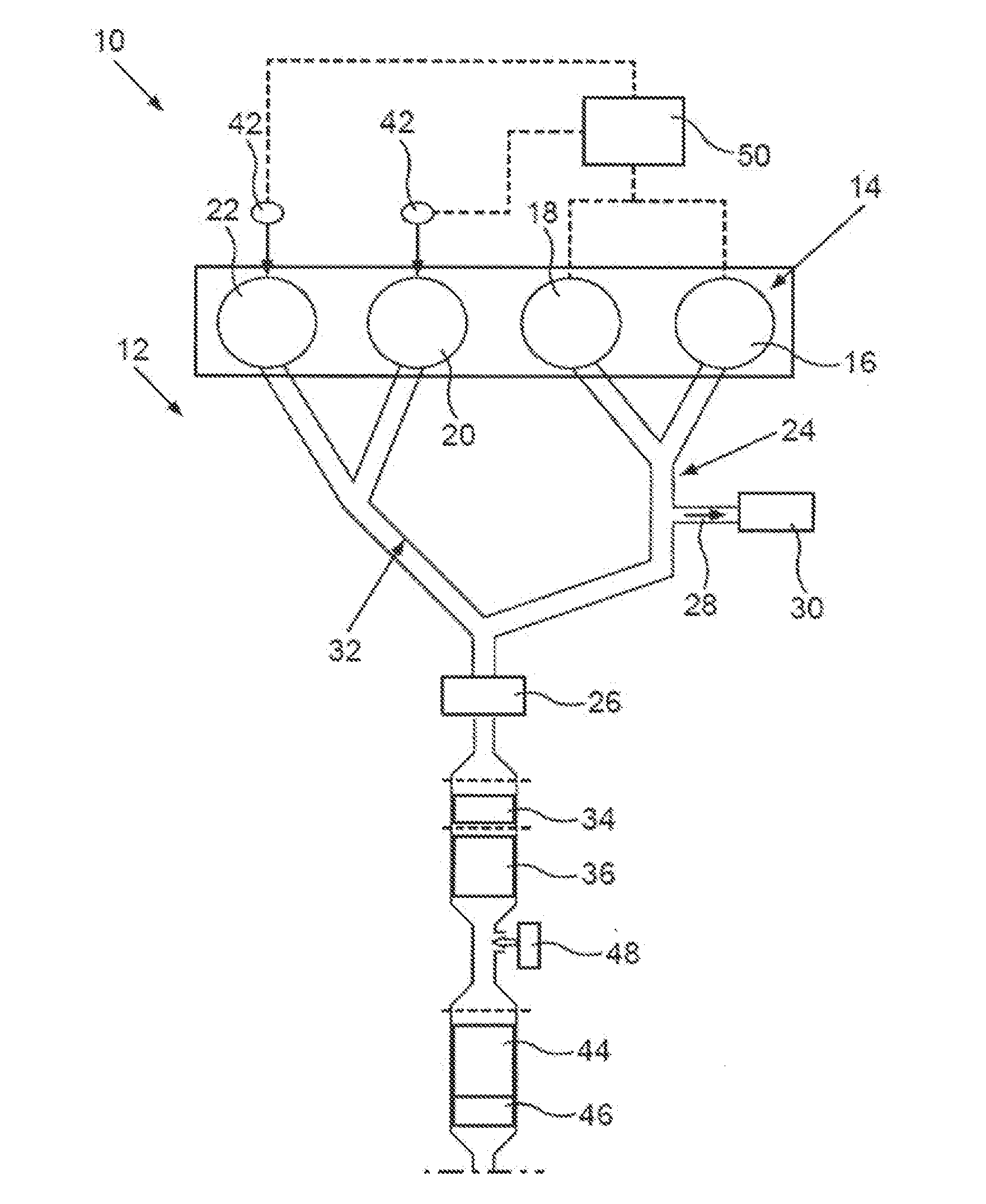
[0051]FIG. 1 shows an arrangement 10 of an exhaust gas system 12 in an internal combustion engine 14, designed as a direct-injection 4-stroke diesel engine, of a vehicle, in particular a utility vehicle. The diesel engine 14 has four cylinders 16, 18, 20, 22 in the present case. A group of two (in the present case) first cylinders 16, 18 is fluidically coupled to a turbine 26 of an exhaust gas turbocharger via an exhaust gas line 24. An exhaust gas recirculation line 28 branches off from the exhaust gas line 24 into which the exhaust gas of the two first cylinders 16, 18 passes. The exhaust gas recirculation line 28 is designed as a high-pressure exhaust gas recirculation line in the present case; however, in addition a low-pressure exhaust gas recirculation may be provided. The quantity of exhaust gas recirculated into a feed air tract (not shown) of the internal combustion engine 14 may be set via an exhaust gas recirculation valve 30, which is shown only schematically.

[0052]The o...


PUM


Abstract

A method for operating an internal combustion engine involves using an injection valve to post-inject fuel into at least one cylinder of the internal combustion engine in order to help regenerate a particulate filter that is arranged in an exhaust system of the internal combustion engine, downstream of an oxidation catalyst. A closing moment of a discharge valve of a cylinder of the internal combustion engine is advanced when the temperature of the oxidation catalyst is in a first temperature range, and the post-injections are performed when the temperature of the oxidation catalyst is in a second temperature range, an upper limit of the first temperature range having a lower value that an upper limit of the second temperature range.

Description

BACKGROUND AND SUMMARY OF THE INVENTION[0001]Exemplary embodiments of the invention relate to a method for operating an internal combustion engine, and an internal combustion engine which is designed for carrying out the method.[0002]In automotive technology it is customary to filter soot particles from the exhaust gas, in particular from diesel engines, by means of a particle filter. The aim is to avoid an excessive accumulation of filtered particles in the particle filter. Accumulated soot particles in the particle filter may be continuously removed by oxidation, using NO2 and H2O as oxidizing agents, at temperatures above approximately 250° C. This effect is also known as the continuous regeneration trap (CRT) effect, referring to a filter having continuous regeneration. Since the nitrogen oxides contained in the exhaust gas usually consist almost exclusively of NO, it is customary to increase the NO2 portion by oxidizing this NO in an oxidation catalytic converter upstream from ...

Claims


Application Information

Patent Timeline
IPC IPC(8): F01N3/025F02M25/07F01N9/00F02D41/02F01N3/20
CPCF01N3/025F02D41/024F01N3/2066F02D13/0249F02M25/0718F01N2430/06F01N2430/10F01N9/002F01N3/023F01N3/0231F01N3/103F01N13/02F02D13/0265F02D41/0065F02D41/0245F02D41/025F02D41/029F02D41/047F02D41/405F02D2041/001F02D2200/0802F02D2250/11F02M26/05F02M26/06F02M26/15F02M26/43Y02T10/12Y02T10/40
Inventor KOCH, THOMASMASSNER, ALEXANDERZIMMERMANN, FRANKZOELLER, HERBERT
Owner DAIMLER TRUCK AG
Why Eureka
Try Eureka