
Honeycomb structure body

a technology of honeycomb and structure body, which is applied in the direction of machines/engines, physical/chemical process catalysts, separation processes, etc., can solve the problems of reducing the productivity of honeycomb structure bodies having a correct roundness, easy breakage of honeycomb structure bodies, and difficulty in producing honeycomb structure bodies with correct roundness, so as to improve the mechanical strength of honeycomb structures, avoid the structure of honeycombs, and prevent the generation of defects in honeycomb structures

Active Publication Date: 2015-10-01
DENSO CORP
View PDF1 Cites 17 Cited by
  • Summary
  • Abstract
  • Description
  • Claims
  • Application Information

AI Technical Summary

Benefits of technology

The present invention provides a honeycomb structure body that has excellent strength and prevents catalyst clogging. The honeycomb structure body has multiple cell density sections formed in parallel rows, which results in a uniform gas flow distribution. The boundary wall formed between the cell density sections increases mechanical strength and prevents damage during manufacturing or conveyance. The cell density sections with boundary cells have a larger size to prevent catalyst clogging, which decreases pressure loss and improves productivity.

Problems solved by technology

However, the boundary section formed between the adjacent cell density sections having different cell densities in the honeycomb structure body previously described has an insufficient strength around the boundary section, and there is a possible drawback of the honeycomb structure body easily breaking due to external stress.
For this reason, it is difficult to produce a honeycomb structure body having a correct roundness.
This reduces a productivity of honeycomb structure bodies having a correct roundness.
However, because small sized cells having a small cross section are formed near the boundary wall section, catalyst clogging (in which a cell is clogged with catalyst) occurs in the small sized cells when catalyst is supported in the honeycomb structure body during the manufacturing process of producing honeycomb structure bodies.
As a result, such small sized cells having a small cross section formed adjacent to the boundary wall section are clogged with catalyst.
This increases a pressure loss of the honeycomb structure body.
In addition, the formation of catalyst-clogged cells causes a reduction in exhaust gas flow in some sections which support catalyst and are clogged by catalyst.
This is a waste of catalyst because catalyst is used in the unnecessary sections in the honeycomb structure body.

Method used


Image

  • Honeycomb structure body
  • Honeycomb structure body
  • Honeycomb structure body

Examples


first exemplary embodiment

[0058]A description will be given of various test samples according to exemplary embodiment of the honeycomb structure body and comparative examples.

[0059]The first exemplary embodiment prepared test samples E1 to E6 as the honeycomb structure body according to the first exemplary embodiment and comparative examples C1 to C5, and evaluated these samples.

[0060]A description will now be given of the test samples E1 to E6 according to the first exemplary embodiment.

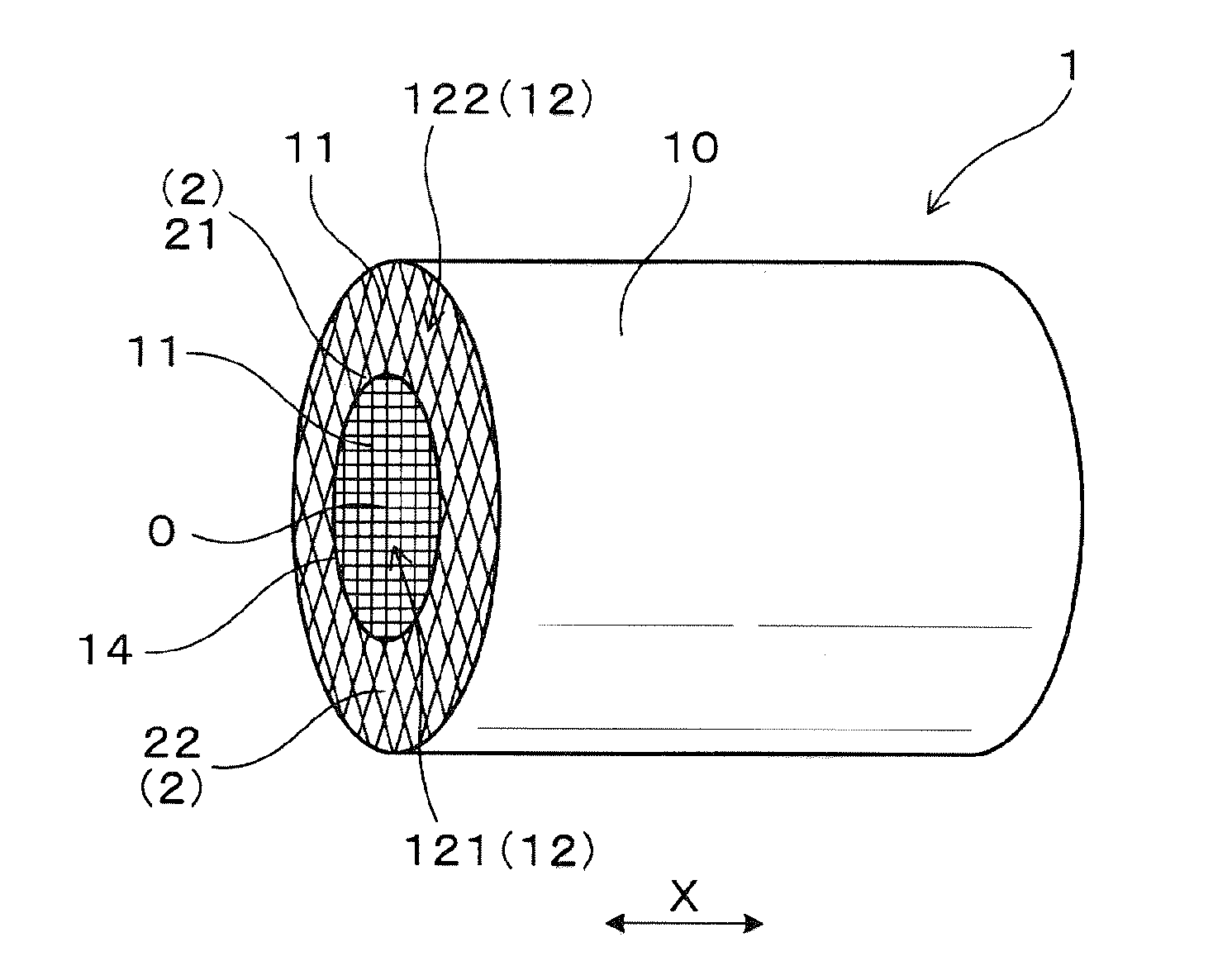
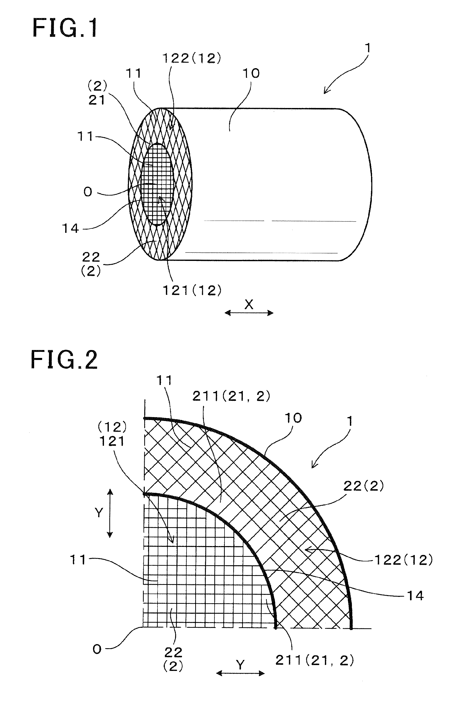
[0061]FIG. 1 is a perspective view showing an overall honeycomb structure body 1 according to the first exemplary embodiment. FIG. 2 is a view showing a partial cross section in a radial direction of the honeycomb structure body (test samples E1 to E6) according to the first exemplary embodiment shown in FIG. 1.

[0062]As shown in FIG. 1 and FIG. 2, the honeycomb structure body 1 is made of ceramics and has an outer peripheral wall 10 having a cylindrical shape, partition walls 11 arranged in a lattice shape in the interior se...

second exemplary embodiment

[0130]A description will be given of the honeycomb structure body according to the second exemplary embodiment.

[0131]The honeycomb structure body according to the second exemplary embodiment (test samples E7 to E10, and comparative samples C6 to C9) has the first and second cell density sections having different cell densities.

[0132]In particular, the first cell density section in the honeycomb structure body (test samples E7 to E10, and comparative samples C6 to C9) according to the second exemplary embodiment is different in cell density from the first cell density section of the honeycomb structure body according to the first exemplary embodiment (test samples E1 to E6, and comparative samples C1 to C5). Further, the second cell density section in the honeycomb structure body (test samples E7 to E10, and comparative samples C6 to C9) according to the second exemplary embodiment is different in cell density from the second cell density section of the honeycomb structure body (test...

third exemplary embodiment

[0137]A description will be given of the honeycomb structure body according to the third exemplary embodiment.

[0138]The honeycomb structure body according to the second exemplary embodiment (test samples E11 to E14, and comparative samples C10 to C13) has two cell density sections, each having a different cell density. In particular, the first cell density section in the honeycomb structure body according to the third exemplary embodiment (test samples E11 to E14, and comparative samples C10 to C13) is different in cell density from the first cell density section of the honeycomb structure body according to the first and second exemplary embodiment previously described. Further, the second cell density section in the honeycomb structure body according to the third exemplary embodiment (test samples E11 to E14, and comparative samples C10 to C13) is different in cell density from the second cell density section of the honeycomb structure body according to the first and second exempla...


PUM

PropertyMeasurementUnit
Lengthaaaaaaaaaa
Diameteraaaaaaaaaa
Radiusaaaaaaaaaa

Abstract

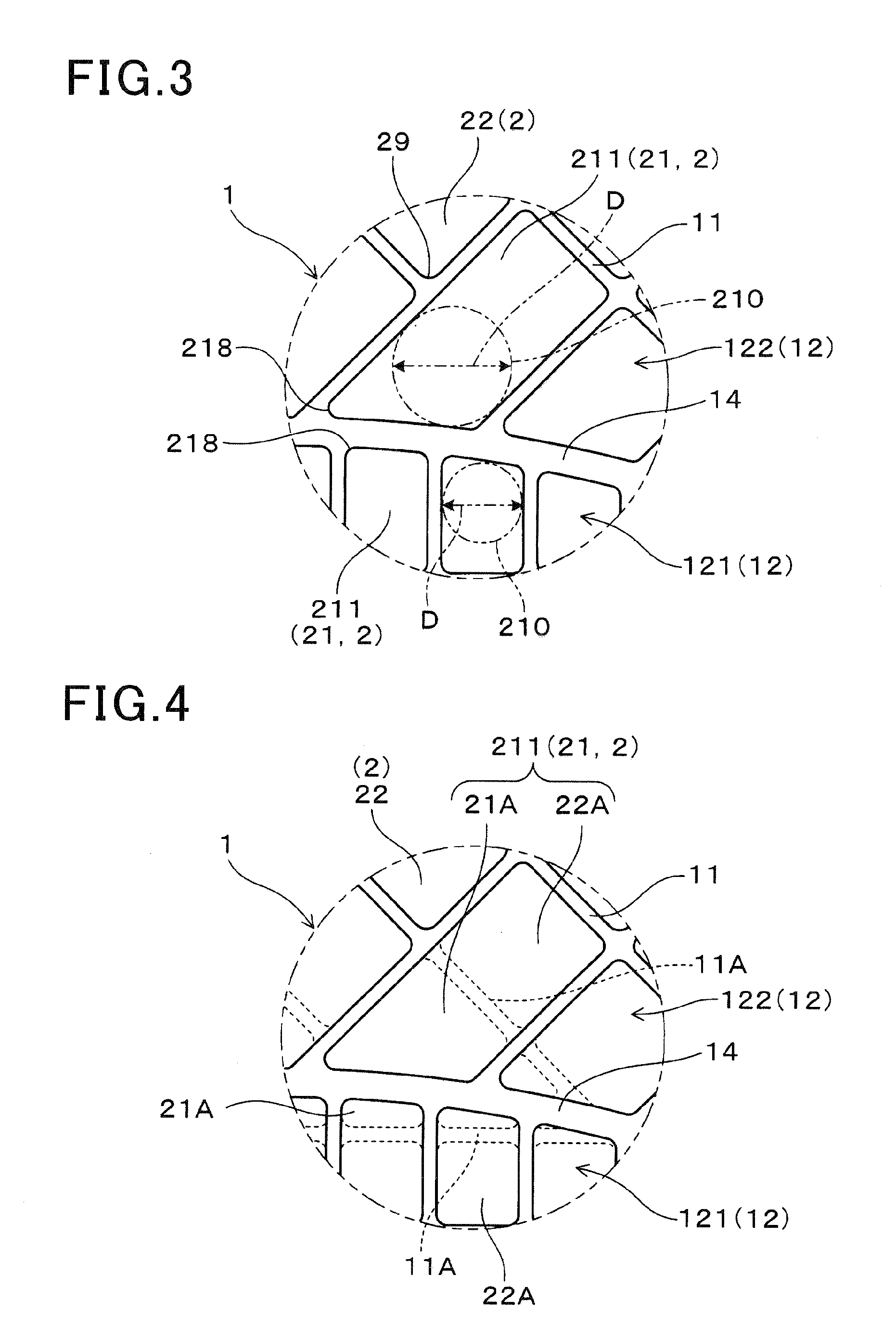
A honeycomb structure body has a cylindrical outer peripheral wall, partition walls and cells. The cells are surrounded by the partition walls. In a radial cross section of the honeycomb structure body, the cells is divided into cell density sections having different cell densities formed from a central section to the outer peripheral wall. A boundary wall is formed between two cell density sections. Each cell density section has boundary cells and interior cells. The boundary cells are in contact with the boundary wall. The interior cells are not in contact with the boundary wall. In the radial cross section of the honeycomb structure body, an inscribed circle of each of the boundary cells has a diameter of not less than 0.5 mm. Further, an inscribed circle of an interior cell adjacent to the boundary cell also has a diameter of not less than 0.5 mm.

Description

CROSS-REFERENCE TO RELATED APPLICATION[0001]This application is related to and claims priority from Japanese Patent Applications No. 2014-63095 filed on Mar. 26, 2014, and No. 2014-243691 filed on Dec. 2, 2014 the contents of which are hereby incorporated by reference.BACKGROUND OF THE INVENTION[0002]1. Field of the Invention[0003]The present invention relates to honeycomb structure bodies having a structure in which the honeycomb structure body has partition walls to form a plurality of cells, and a radial cross section of the honeycomb structure body, perpendicular to an axial direction along which the cells are formed, is divided into a plurality of cell density sections having different cell densities, and the cells belong to respective cell density sections.[0004]2. Description of the Related Art[0005]There have been known and widely used honeycomb structure bodies as a catalyst supporter, in which catalyst is supported. A honeycomb structure body is mounted to an exhaust gas p...

Claims


Application Information

Patent Timeline
IPC IPC(8): F01N3/035B01J35/04B01D46/24
CPCF01N3/035B01D46/2451B01D46/247B01D2046/2488B01D46/2474B01J35/04B01D46/2462Y10T428/24149B01D46/2486B01D46/2484B01D46/2482B01J35/56
Inventor TAMAI, KOJIOONISHI, MASAHIRO
Owner DENSO CORP
Learn More