Physical quantity detection circuit, physical quantity detecting device, electronic apparatus, and moving object

a detection circuit and physical quantity technology, applied in the direction of acceleration measurement using interia force, devices using electric/magnetic means, instruments, etc., can solve the problems of reduced possibility of detection accuracy, and generated rotational vibration about the detection axis, so as to reduce the possibility and reduce the effect of detection accuracy

Inactive Publication Date: 2015-10-01
SEIKO EPSON CORP
View PDF1 Cites 10 Cited by
  • Summary
  • Abstract
  • Description
  • Claims
  • Application Information

AI Technical Summary

Benefits of technology

[0026]The electronic apparatus and the moving object according to these application examples include the physical quantity detection circuit or the physical quantity detecting device with the reduced possibility of lower...

Problems solved by technology

However, in the physical quantity detecting device of related art like the vibration gyro sensor disclosed in Patent Document 1, a rotational vibration is generated about the detection axis of the vibrating element due to resonance of the mounting board or the like.
Therefore, according to the physical quantity detection circuit of this application example, even when the rotational vibration at the frequency close to the detuning frequency of the vibrating element is applied, a possibility of lower detection accuracy may be reduced.
According to the physical quantity detecting devi...

Method used


Image

  • Physical quantity detection circuit, physical quantity detecting device, electronic apparatus, and moving object
  • Physical quantity detection circuit, physical quantity detecting device, electronic apparatus, and moving object
  • Physical quantity detection circuit, physical quantity detecting device, electronic apparatus, and moving object

Examples


first embodiment

1-1. First Embodiment

Functional Configuration of Physical Quantity Detecting Device

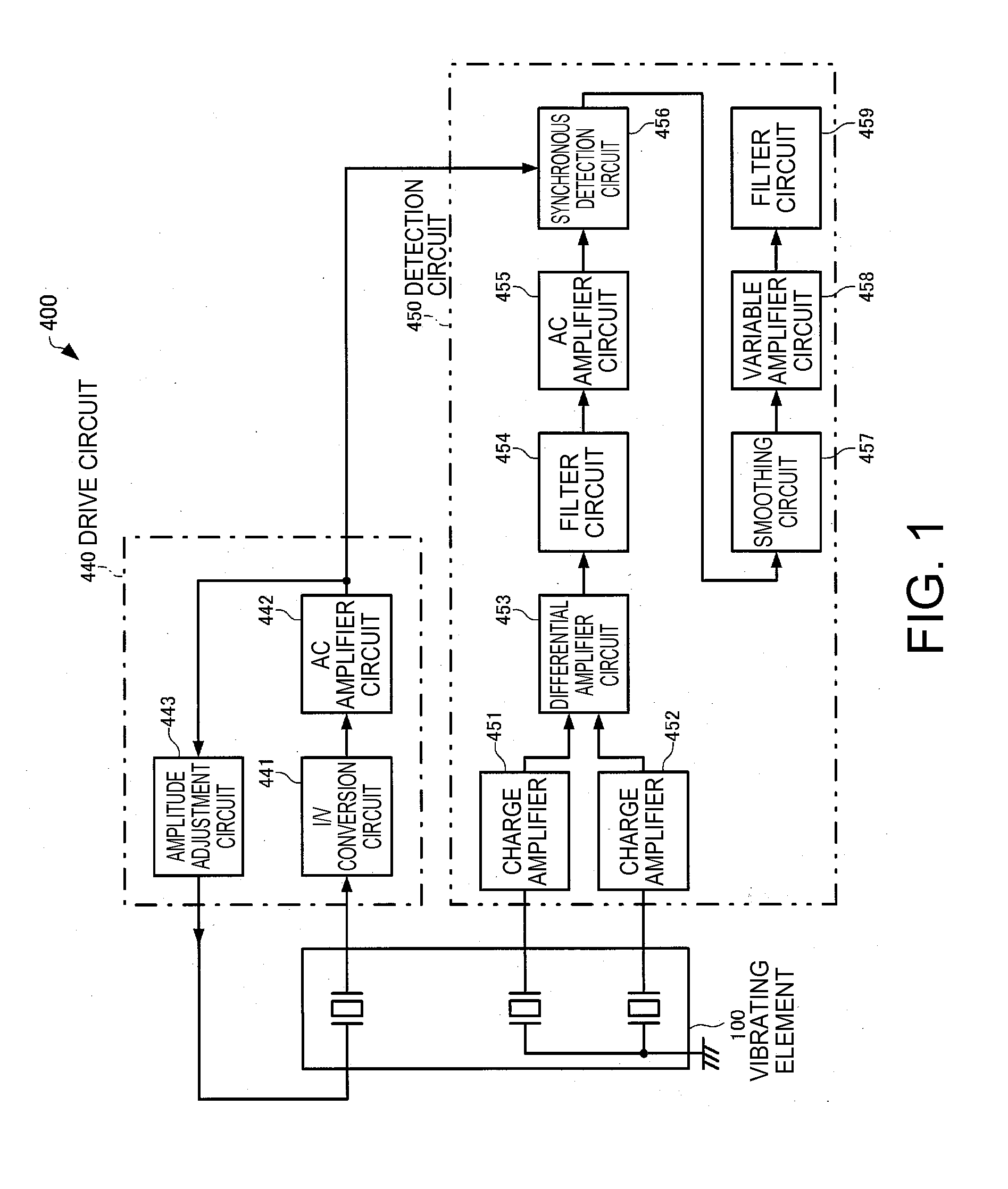
[0048]FIG. 1 is a functional block diagram of a physical quantity detecting device according to the first embodiment. As shown in FIG. 1, a physical quantity detecting device 400 according to the embodiment includes a vibrating element 100, a drive circuit 440 for driving to vibrate drive vibrating arms 220, 222 (see FIGS. 2 and 3) of the vibrating element 100, and a detection circuit 450 (an example of a physical quantity detection circuit) for detecting detection vibrations generated in detection vibrating arms 230, 232 of the vibrating element 100 when an angular velocity (an example of physical quantity) is applied. The drive circuit 440 and the detection circuit 450 may be realized by a one-chip IC or respectively realized by individual IC chips.

[0049]The drive circuit 440 has an I / V conversion circuit (current-voltage conversion circuit) 441, an AC amplifier circuit (alternating-current amplifie...

second embodiment

1-2. Second Embodiment

[0119]A physical quantity detecting device 400 according to the second embodiment is different from that of the first embodiment in the structure of the vibrating element 100. Note that the functional block diagram of the physical quantity detecting device according to the second embodiment is the same as FIG. 1 and the illustration and explanation will be omitted.

Configuration of Vibrating Element

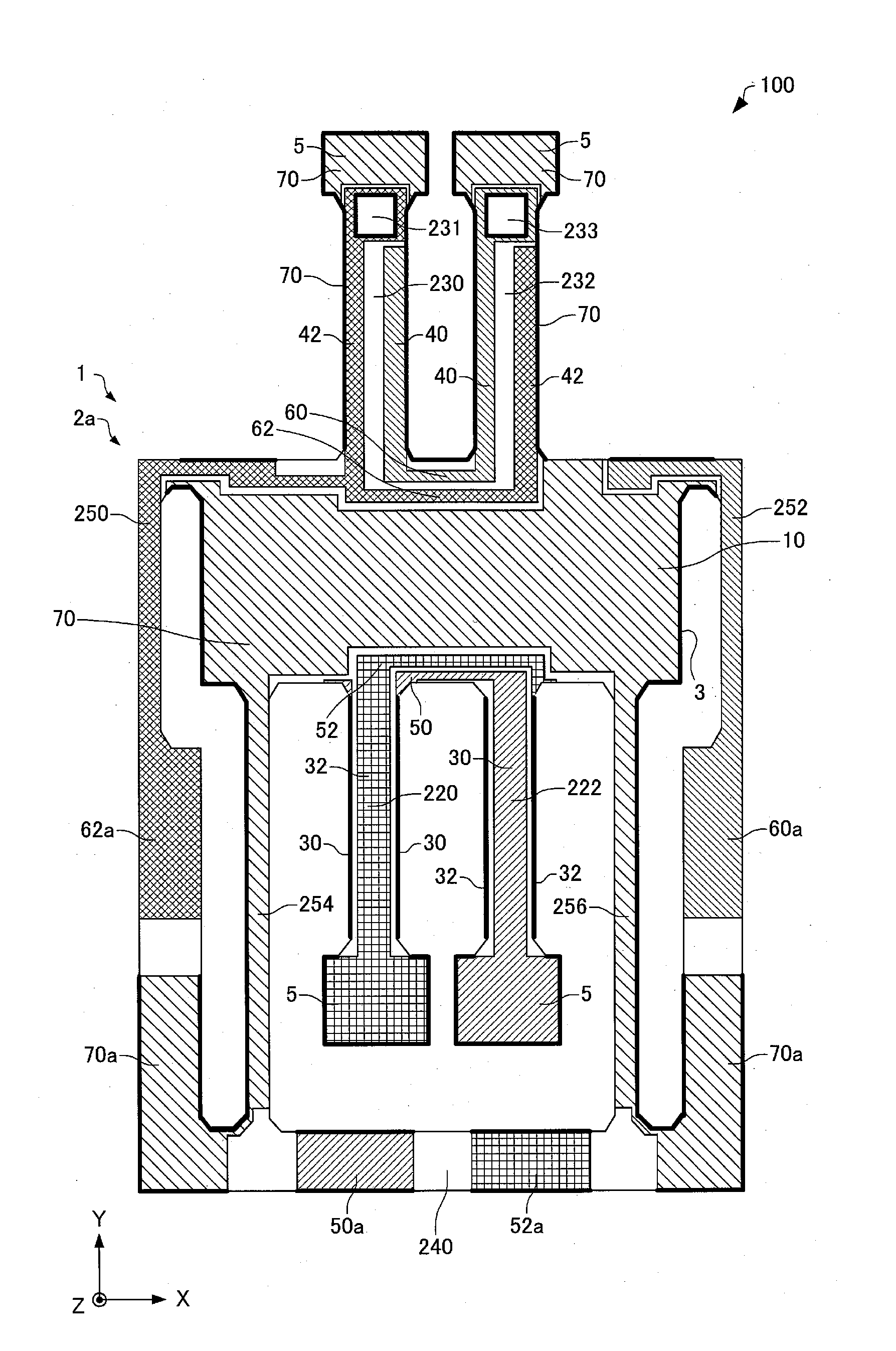
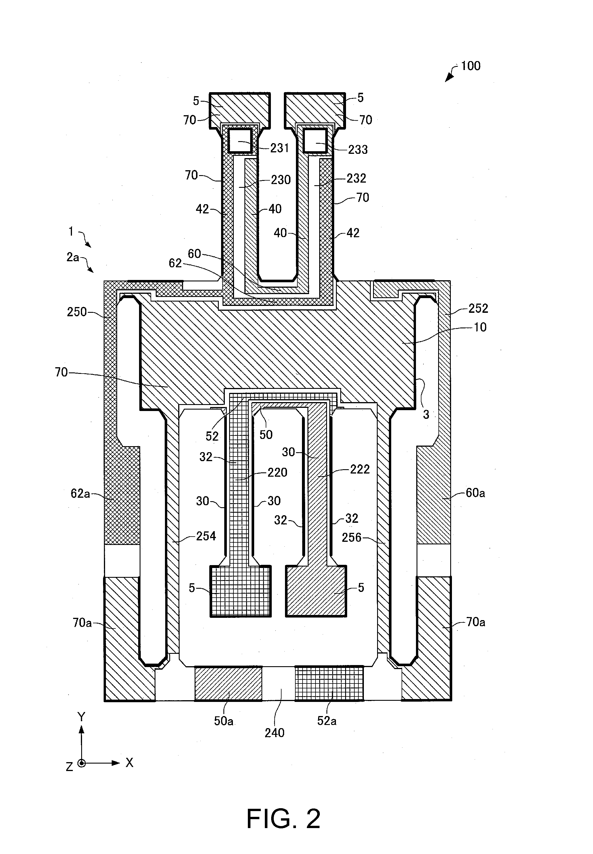
[0120]A vibrating element 100 according to the second embodiment will be explained with reference to the drawings. FIGS. 9 and 10 are plan views schematically showing the vibrating element 100 according to the second embodiment.

[0121]Note that FIG. 9 shows the vibrating element 100 as seen from a first principal surface 2a side for explanation of the configuration on the first principal surface 2a side. FIG. 10 is a transparent view of the vibrating element 100 as seen from the first principal surface 2a side for explanation of the configuration on a second principal ...

third embodiment

1-3. Third Embodiment

[0157]FIG. 13 is a functional block diagram of a physical quantity detecting device 400 according to the third embodiment. In FIG. 13, the same signs are assigned to the same component elements as those in FIG. 1. As shown in FIG. 13, in the physical quantity detecting device 400 according to the third embodiment, the output signals of the differential amplifier circuit 453 are input to the AC amplifier circuit 455 and the signals AC-amplified in the AC amplifier circuit 455 are input to the filter circuit 454.

[0158]Like the first embodiment, the filter circuit 454 functions as a filter part having the cutoff frequency fc between the resonance frequency fdr in the drive mode and the resonance frequency fdt in the detection mode of the vibrating element 100 and containing the resonance frequency fdr in the drive mode in the passband. The filter circuit 454 is formed as a low-pass filter when the vibrating element 100 has the relationship of fdrdt and formed as a ...


PUM


Abstract

A physical quantity detection circuit includes a filter circuit, and a synchronous detection circuit that is provided at a downstream of the filter circuit and detects a signal in response to a physical quantity contained in an output signal of a vibrating element based on a drive signal for driving the vibrating element. The filter circuit has a cutoff frequency between a resonance frequency in a drive mode and a resonance frequency in a detection mode of the vibrating element and contains the resonance frequency in the drive mode in a passband.

Description

BACKGROUND[0001]1. Technical Field[0002]The present invention relates to a physical quantity detection circuit, a physical quantity detecting device, an electronic apparatus, and a moving object.[0003]2. Related Art[0004]Physical quantity detecting devices that detect physical quantities such as angular velocities and acceleration using vibrating elements including crystal vibrators (piezoelectric vibrators) and MEMS (Micro Electro Mechanical Systems) vibrators are known.[0005]For example, as angular velocity detecting devices for detecting rotation angular velocities of rotation systems, vibration gyro sensors using piezoelectric elements such as crystal vibrators are incorporated in various electronic apparatuses and used for car navigation, hand shake detection at imaging, etc.[0006]The vibration gyro sensor is proposed in Patent Document 1 (JP-A-2010-256332), for example.[0007]However, in the physical quantity detecting device of related art like the vibration gyro sensor disclo...

Claims


Application Information

Patent Timeline
IPC IPC(8): G01C19/5642
CPCG01C19/5642G01C19/5607G01C19/5776G01C19/5614
Inventor NISHIZAWA, RYUTANAKAGAWA, KEIJI
Owner SEIKO EPSON CORP
Why Eureka
Try Eureka