Check patentability & draft patents in minutes with Patsnap Eureka AI!

Integrated MEMS inertial sensing device

Active Publication Date: 2015-10-01
MCUBE INC
View PDF9 Cites 11 Cited by
  • Summary
  • Abstract
  • Description
  • Claims
  • Application Information

AI Technical Summary

Benefits of technology

This patent describes a system for controlling the amplitude of signals in a gyroscope. The system uses a rectifier to detect the signal from a phase shifter. A low pass filter is applied to the signal to create an average envelope of the feedback signal. The average amplitude is then compared with a reference signal. The system uses a Proportional, Integral, Derivative (PID) controller to adjust the amplitude to match the reference signal. The PID controller has both a proportional and an integrator function, allowing for both fast and slow filtering of the signals. This system helps to quickly and smoothly transition the gyroscope during power-up and ensures optimal performance.

Problems solved by technology

Although highly successful, ICs and in particular MEMS still have limitations.
Similar to IC development, MEMS development, which focuses on increasing performance, reducing size, and decreasing cost, continues to be challenging.
Additionally, applications of MEMS often require increasingly complex microsystems that desire greater computational power.
Unfortunately, such applications generally do not exist.

Method used


Image

  • Integrated MEMS inertial sensing device
  • Integrated MEMS inertial sensing device
  • Integrated MEMS inertial sensing device

Examples


Embodiment Construction

[0019]The present invention is directed to MEMS (Micro-Electro-Mechanical-Systems). More specifically, embodiments of the invention provide methods and structures for improving integrated MEMS devices, including inertial sensors and the like. Merely by way of example, the MEMS device can include at least an accelerometer, a gyroscope, a magnetic sensor, a pressure sensor, a microphone, a humidity sensor, a temperature sensor, a chemical sensor, a biosensor, an inertial sensor, and others. But it will be recognized that the invention has a much broader range of applicability.

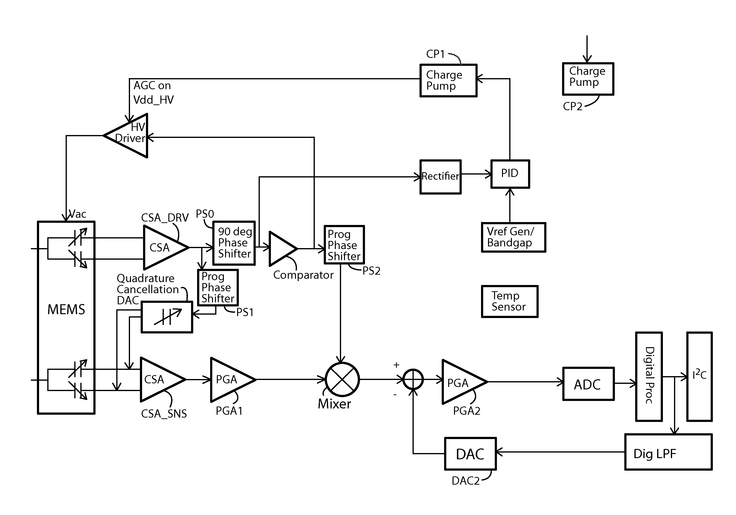
[0020]The present invention includes a drive loop configuration for an integrated MEMS inertial sensing device (i.e. gyroscope). According to an embodiment, a Gyroscope or inertial sensing system has a drive element that needs to resonate continuously at desired frequency and amplitude. To maintain this oscillation of MEMS element, the drive loop invented consists of a Signal acting as driving force to a MEMS res...


PUM


Abstract

An integrated MEMS inertial sensing device can include a MEMS inertial sensor with a drive loop configuration overlying a CMOS IC substrate. The CMOS IC substrate can include an AGC loop circuit coupled to the MEMS inertial sensor. The AGC loop acts in a way such that generated desired signal amplitude out of the drive signal maintains MEMS resonator velocity at a desired frequency and amplitude. A benefit of the AGC loop is that the charge pump of the HV driver inherently includes a ‘time constant’ for charging up of its output voltage. This incorporates the Low pass functionality in to the AGC loop without requiring additional circuitry.

Description

CROSS-REFERENCES TO RELATED APPLICATIONS[0001]The present application claims priority to and incorporates by reference, for all purposes, the following pending patent application: U.S. Provisional App. 61 / 755,451, filed Jan. 22, 2013 and U.S. Provisional App. 61 / 755,450, filed Jan. 22, 2013.BACKGROUND OF THE INVENTION[0002]The present invention is directed to MEMS (Micro-Electro-Mechanical-Systems). More specifically, embodiments of the invention provide methods and structure for improving integrated MEMS devices, including inertial sensors and the like. Merely by way of example, the MEMS device can include at least an accelerometer, a gyroscope, a magnetic sensor, a pressure sensor, a microphone, a humidity sensor, a temperature sensor, a chemical sensor, a biosensor, an inertial sensor, and others. But it will be recognized that the invention has a much broader range of applicability.[0003]Research and development in integrated microelectronics have continued to produce astounding...

Claims


Application Information

Patent Timeline
IPC IPC(8): G01C19/5712B81B7/00B81B7/02
CPCG01C19/5712B81B7/02B81B2201/0242B81B2201/0235B81B7/008
Inventor RASTEGAR, ALI J.BHANDARI, SANJAY
Owner MCUBE INC
Features
  • R&D
  • Intellectual Property
  • Life Sciences
  • Materials
  • Tech Scout
  • Unparalleled Data Quality
  • Higher Quality Content
  • 60% Fewer Hallucinations
Learn More