

Magnetic resonance imaging apparatus
a magnetic resonance imaging and apparatus technology, applied in the field of magnetic resonance imaging (mri) technique, can solve the problems of difficult to accurately estimate the resonance frequency fsub>0/sub>, and not disclose a specific method with respect to the resonance frequency difference, and achieve the effect of high accuracy
- Summary
- Abstract
- Description
- Claims
- Application Information
AI Technical Summary
Benefits of technology
Problems solved by technology
Method used
Image

Examples
first embodiment
[0028]Hereinafter, a first embodiment to which the invention is applied will be described. Hereinafter, in all the drawings illustrating embodiments of the invention, basically the same reference numerals are given to components having the same functions, and description thereof will not be repeated.
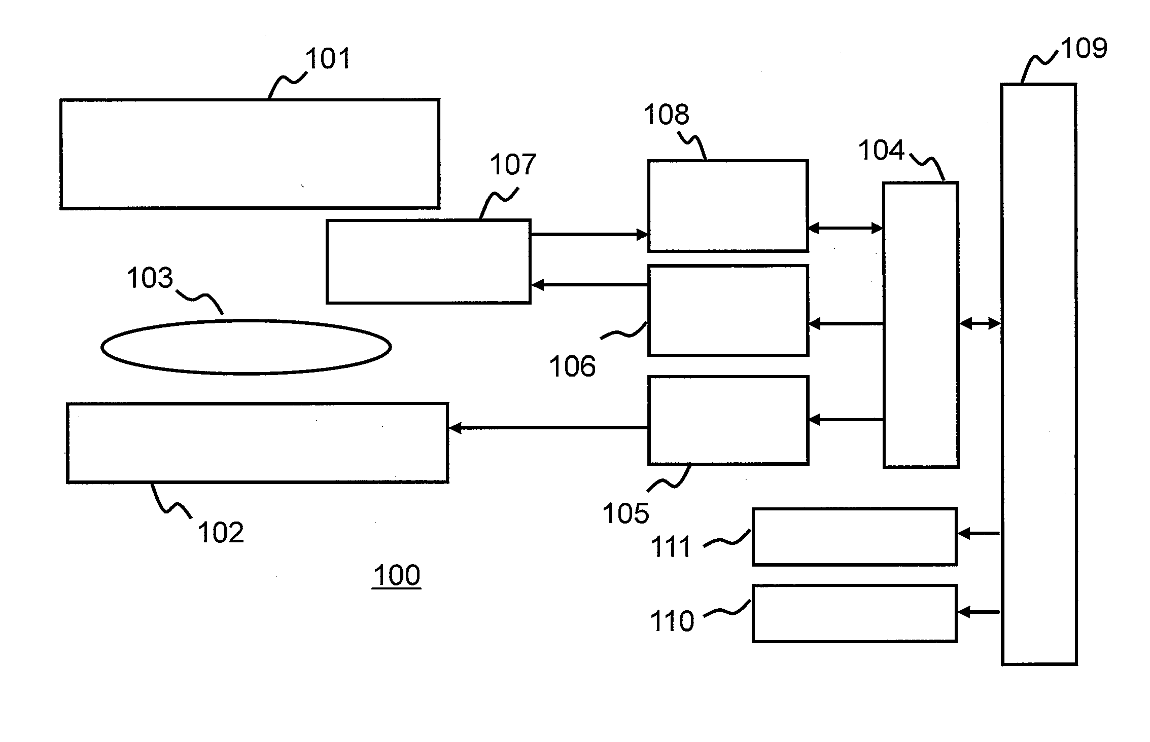
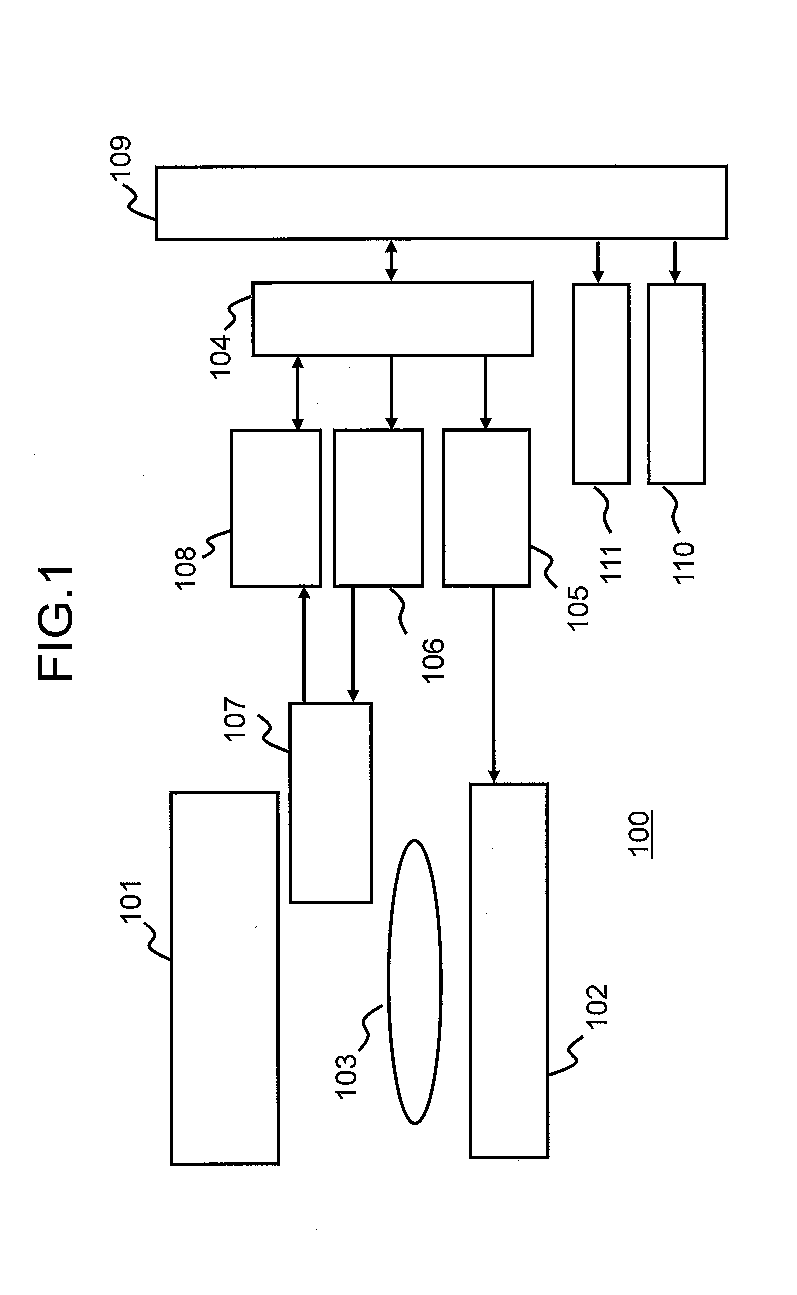
[0029]First, an MRI apparatus according to the present embodiment will be described. FIG. 1 is a block diagram illustrating a schematic configuration of an MRI apparatus 100 according to the present embodiment. The MRI apparatus 100 includes a magnet 101 that generates a static magnetic field, a gradient coil 102 that generates a magnetic field gradient, a sequencer 104, a magnetic field gradient power supply 105, a radio frequency magnetic field generator 106, a transmit / receive coil 107 that emits s radio frequency magnetic field and detects a nuclear magnetic resonance signal, a receiver 108, a computer 109, a display 110, and a storage 111. The transmit / receive coil 107 is shown as a...
modification example 1
[0110]In the above-described embodiment, all of the subject parameters and the apparatus parameters used as the variables of the signal function fs are estimated. However, a part of the parameters may be calculated by a different method, and then, the remaining parameters may be estimated using the above-described method.
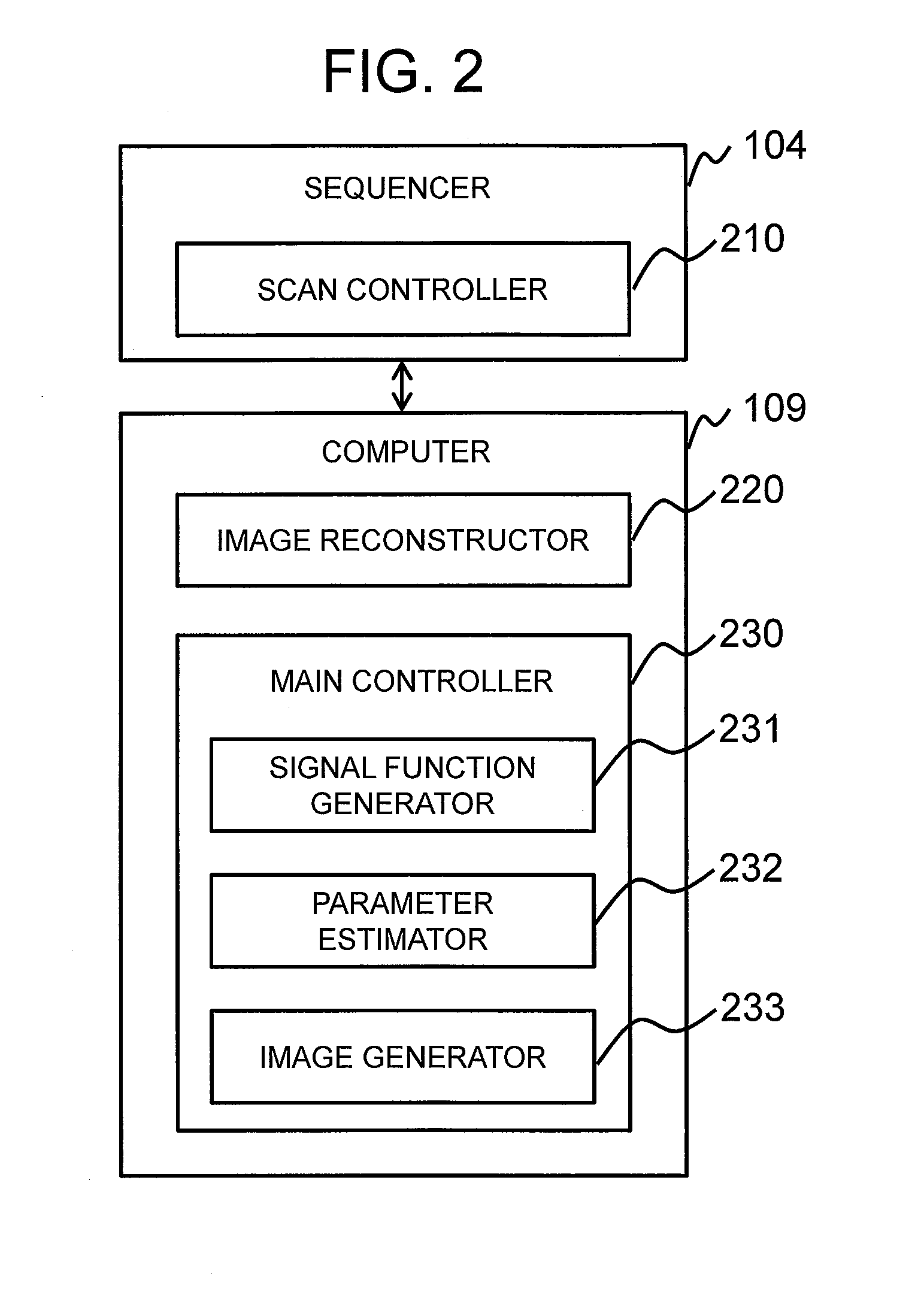
[0111]That is, the parameter estimating unit 232 may be configured to estimate only parameters incapable of being analytically calculated, among the subject parameters and the apparatus parameters, using the above-described method.
[0112]For example, the map of B1 may be calculated by a method called a double angle method (DAM). The DAM method is a method for calculating B1 by the following Formula (6), using luminance values I1 and I2 of images captured at flip angles (FA) a and 2a.
B1=arc cos(I2 / (2I1)) / α (6)
[0113]In this case, B1 is calculated by the DAM method, and only the remaining subject parameters and apparatus parameters (for example, T1 and T2, Δf0, a) are...
modification example 2
[0115]Further, in the above-described embodiment, the parameter estimator 232 changes all of the scan parameters (FA, TR, and 0) which serve as the variables of the signal function fs when estimating the subject parameters and the apparatus parameters, to thereby obtain plural images. However, the invention is not limited to this method. Plural reconstructed images may be obtained by changing at least one scan parameter.
[0116]If TR is changed in the BASG sequence 300, the influence of the chemical shift may occur, similar to RSSG. Thus, when water and fat are mixed in pixels so that the influence cannot be ignored, in the parameter estimation process, the parameter estimator 232 may estimate the subject parameters and the apparatus parameters using the captured image while changing only FA and θ in a state where TR is constant.
[0117]With such a configuration, it is possible to estimate f0 without the influence of the chemical shift.
PUM
 Abstract
Description
Claims
Application Information