Optical member, polarizing plate set, and liquid crystal display apparatus
a technology of polarizing plate and optical member, which is applied in the direction of optical elements, polarising elements, instruments, etc., can solve the problems of color shift, and light guide plate color change in some cases, and achieve excellent mechanical strength and suppress color shift
- Summary
- Abstract
- Description
- Claims
- Application Information
AI Technical Summary
Benefits of technology
Problems solved by technology
Method used
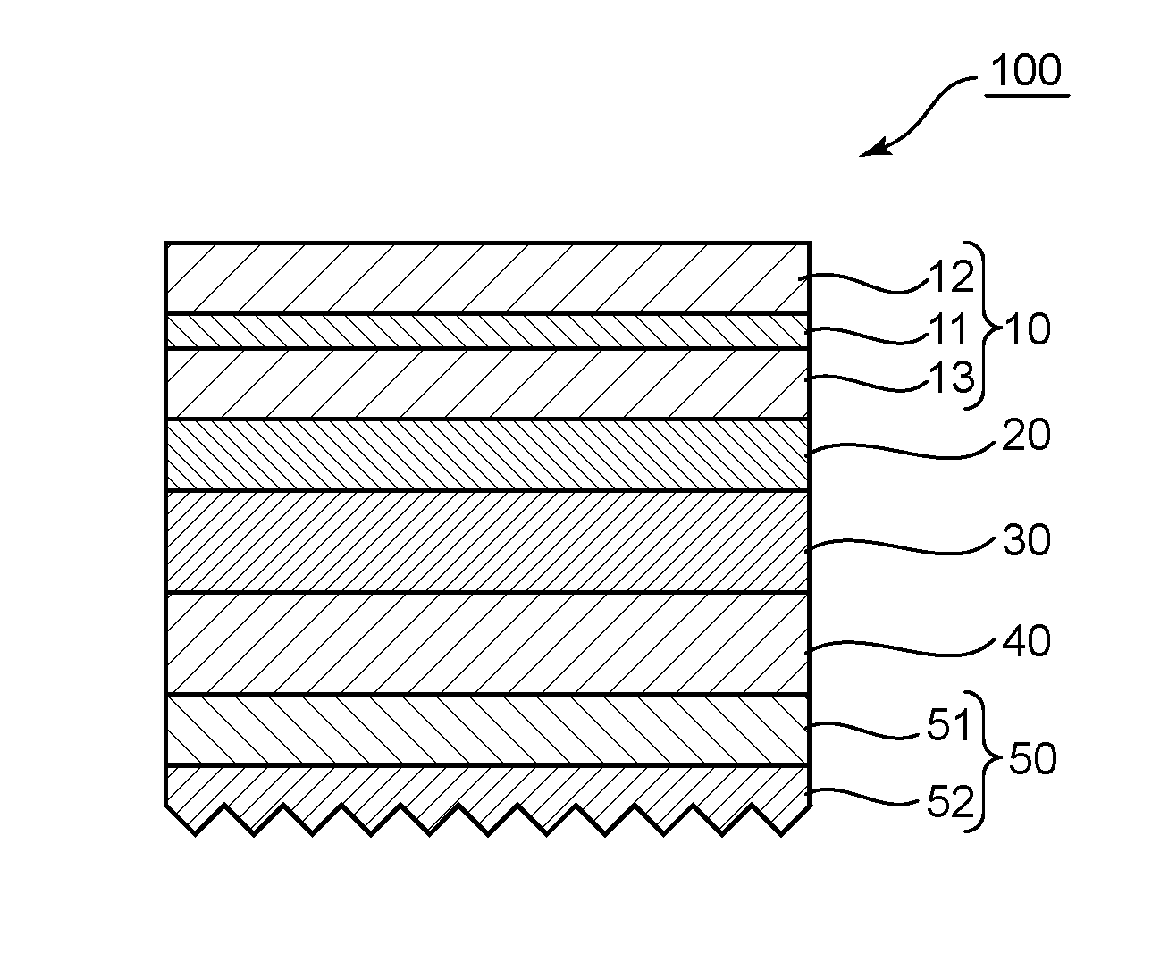
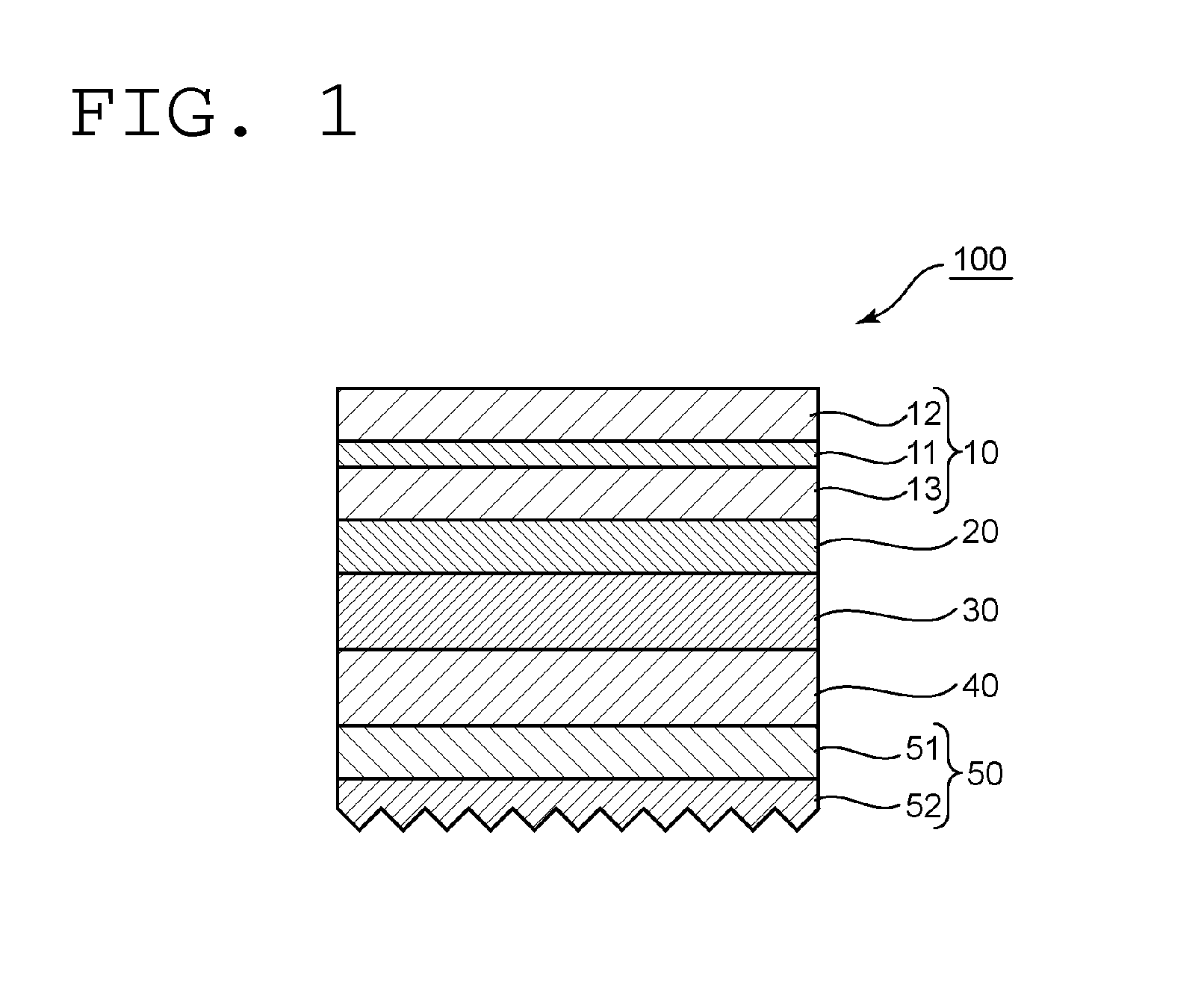
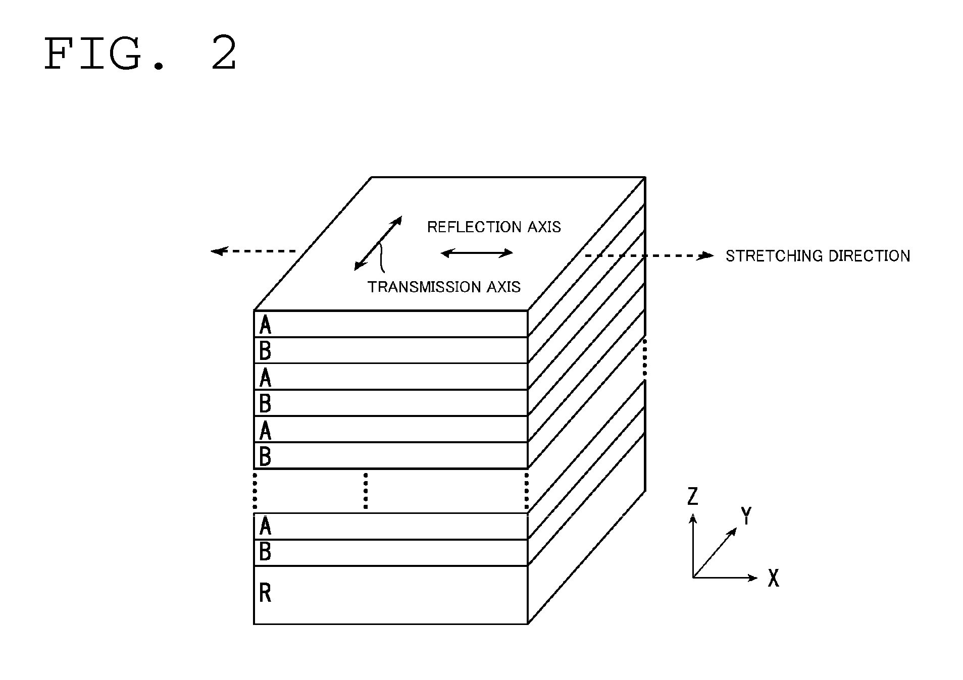
Image

Examples
example 1
Production of Film for First Retardation Layer
[0132]A commercially available polymer film [manufactured by Optes Inc., trade name: “ZeonorFilm ZF14-130 (thickness: 60 μm, glass transition temperature: 136° C.)”] whose main component was a cyclic polyolefin-based polymer was subjected to fixed-end uniaxial stretching in its width direction with a tenter stretching machine at a temperature of 158° C. in such a manner that its film width was 3.0 times as large as the original film width (lateral stretching step). The resultant film was a negative biaxial plate (three-dimensional refractive index: nx>ny>nz) having a fast axis in the conveying direction. The negative biaxial plate had an in-plane retardation of 118 nm and an Nz coefficient of 1.16.
[0133](Production of Film for Second Retardation Layer)
[0134]A pellet-shaped resin of a styrene-maleic anhydride copolymer (manufactured by Nova Chemicals Japan Ltd., product name: “DYLARK D232”) was extruded with a single screw extruder and a ...
example 2
[0149]A liquid crystal display apparatus using the optical member of the present invention was produced in the same manner as in Example 1 except that the optical member was produced so that the thickness of the low refractive index layer became 800 nm.
example 3
[0150]A liquid crystal display apparatus using an optical member was produced in the same manner as in Example 1 except that a low refractive index layer was obtained as described below. That is, an aerogel layer was produced on the surface of the prism sheet on the side opposite to the prism portion by utilizing a spring-back phenomenon, and the layer was used as the low refractive index layer. The aerogel layer was produced in accordance with the procedure described in Example 1 of Japanese Patent Application Laid-open No. 2006-011175.
PUM
| Property | Measurement | Unit |
|---|---|---|
| refractive index | aaaaa | aaaaa |
| thickness | aaaaa | aaaaa |
| light diffusion pressure-sensitive | aaaaa | aaaaa |
Abstract
Description
Claims
Application Information