
Image processing system for generating information by image recognition and related method

Active Publication Date: 2015-10-01
WISTRON CORP
View PDF10 Cites 8 Cited by
  • Summary
  • Abstract
  • Description
  • Claims
  • Application Information

AI Technical Summary

Benefits of technology

The image processing system described in this patent allows for separate display of information and other images and capturing of the information display through an image capturing module. The system can recognize the information display and control the host device or input device to execute the corresponding operation. This eliminates the need for a touch panel and solves issues of assembly waste and high cost associated with reconfiguring the display for touch control.

Problems solved by technology

However, a conventional display panel is not capable of touch control, and an additional touch panel has to be disposed on the conventional display panel, so as to perform the touch display module with touch control function.
The touch panel and the related components have to be installed on the conventional display panel, causing waste of time in assembly and high cost.
Therefore, it is an important issue to design a display module capable of utilizing the stylus in touch operation without reconfiguring the display panel.

Method used


Image

  • Image processing system for generating information by image recognition and related method
  • Image processing system for generating information by image recognition and related method
  • Image processing system for generating information by image recognition and related method

Examples


first embodiment

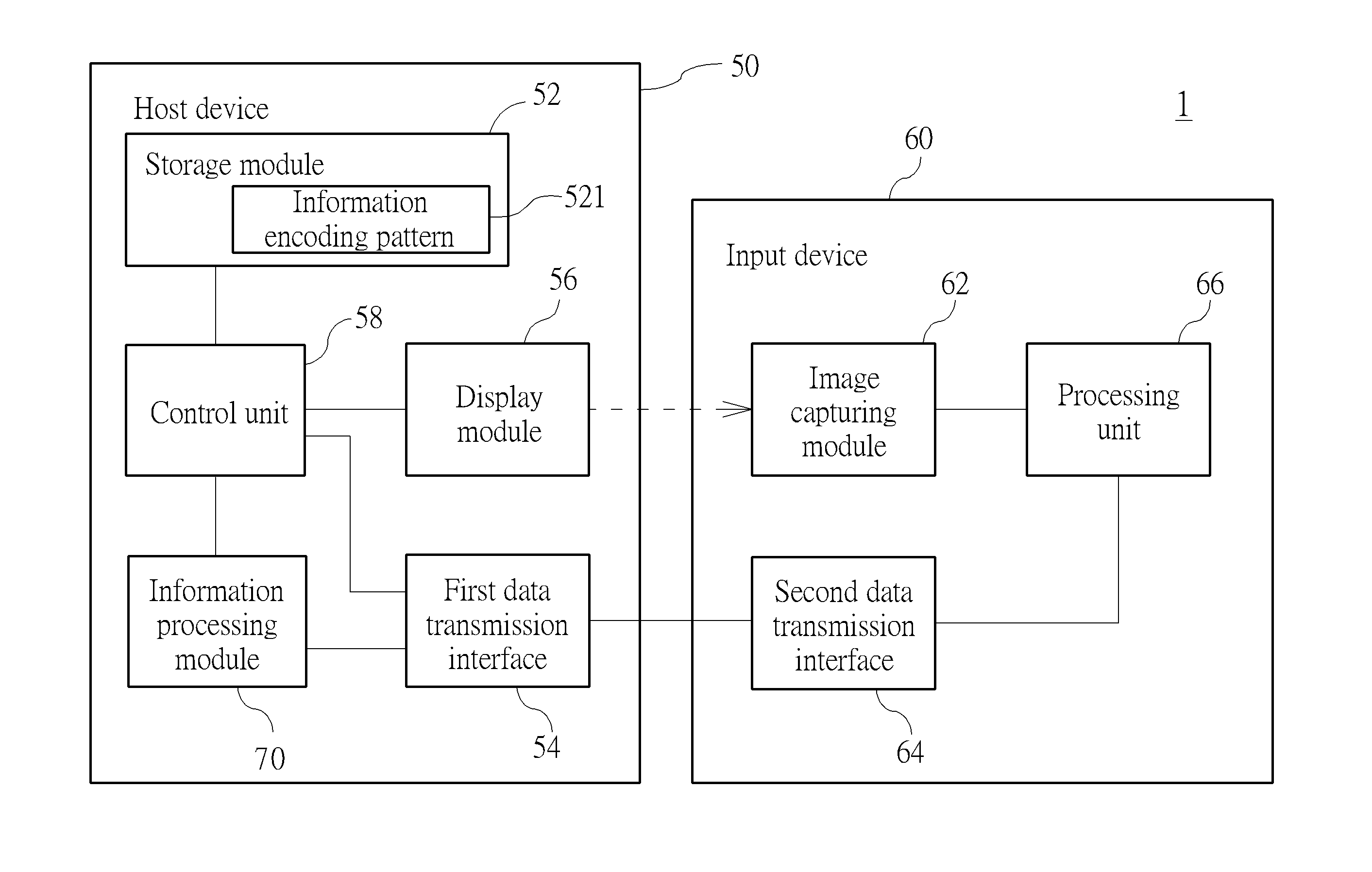
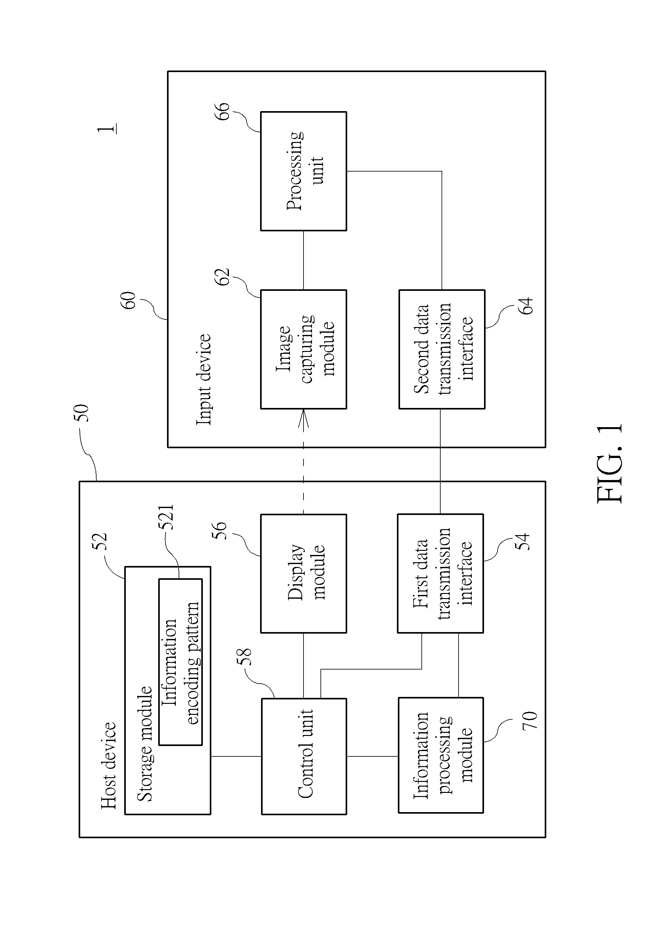
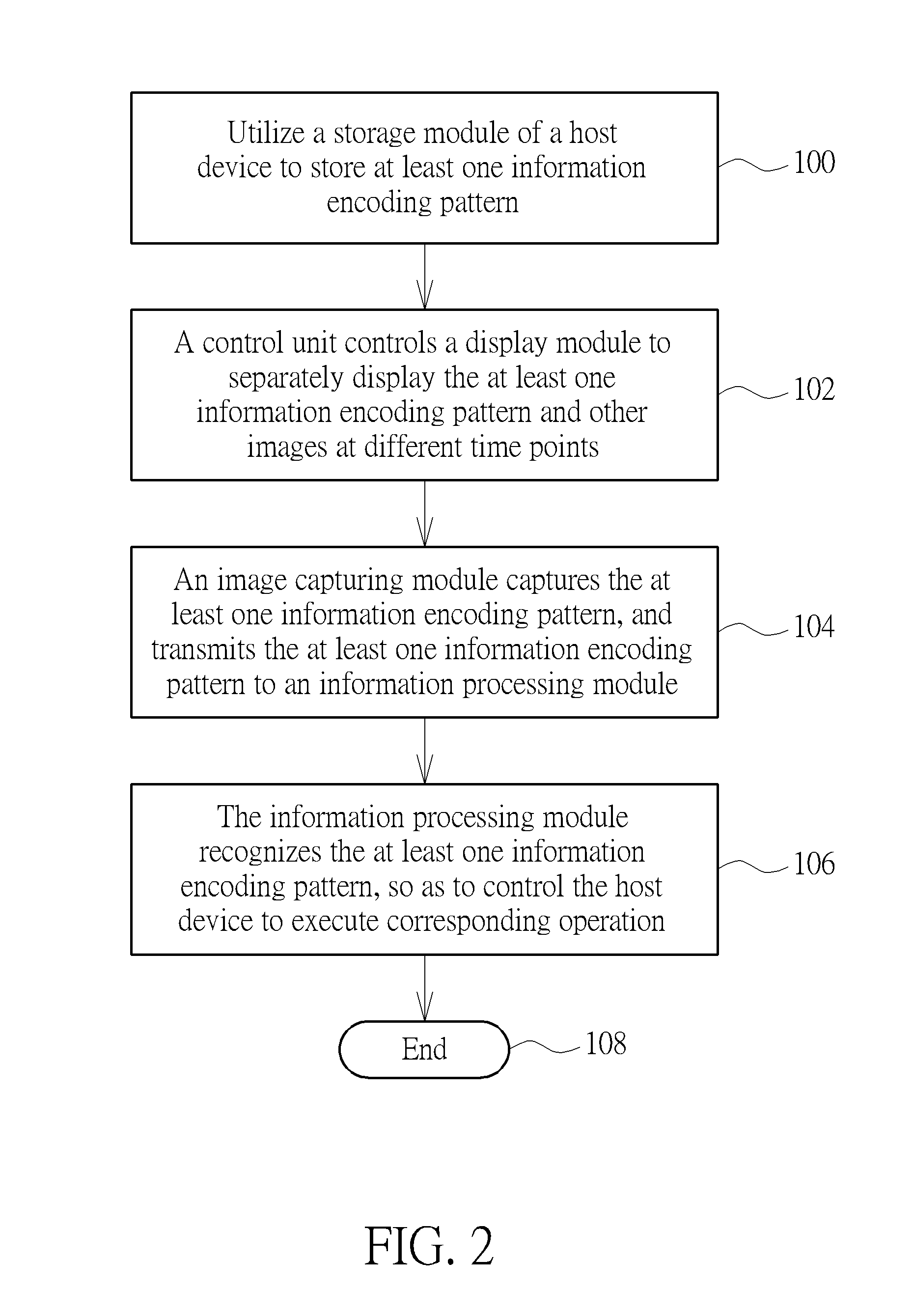
[0032]Please refer to FIG. 1. FIG. 1 is a functional block diagram of an image processing system 1 according to the present invention. The image processing system 1 includes a host device 50, at least one input device 60 and an information processing module 70. The host device 50 includes a storage module 52, a first data transmission interface 54, a display module 56 and a control unit 58. The storage module 52 stores at least one information encoding pattern 521, and the display module 56 is for displaying images. The control unit 58 is electrically connected to the storage module 52, the first data transmission interface 54 and the display module 56. The control unit 58 is for controlling the display module 56 to separately display the at least one information encoding pattern 521 and other images, such as operating system images, at different time points. The input device 60 includes an image capturing module 62, a second data transmission interface 64, and a processing unit 66....

third embodiment

[0045]Please refer to FIG. 1 and FIG. 7. FIG. 7 is a diagram of the display module 56 displaying images at different time points according to the present invention. In this embodiment, the information encoding pattern 521 includes a recognition code information 5213, the image capturing module 62 is a camera module, and the camera module can have a prime lens or a zoom lens. As the aforesaid embodiment, the control unit 58 controls the display module 56 separately to display the information encoding pattern 521 and other images at different time points, and the image capturing module 62 captures the recognition code information 5213 of the information encoding pattern 521 during a time period and transmits the recognition code information 5213 within the time period to the information processing module 70. The information processing module 70 recognizes the received recognition code information 5213, so as to generate a message corresponding to the recognition code information 5213 ...


PUM


Abstract

An image processing system includes a host device, an input device and an information processing module. The host device includes a storage module, a first data transmission interface, a display module and a control unit. The control unit controls the display module to separately display at least one information encoding pattern at different time points. The input device includes an image capturing module, a second data transmission interface and a processing unit. The image capturing module captures a part of the at least one information encoding pattern displayed on the display module. The processing unit controls the second data transmission interface to transmit data to the first data transmission interface. The information processing module recognizes the part of the at least one information encoding pattern captured by the image capturing module, so as to control the host device or the input device to execute corresponding operation.

Description

BACKGROUND OF THE INVENTION[0001]1. Field of the Invention[0002]The present invention relates to an image processing system and a related method, and more specifically, to an image processing system for generating information by image recognition and a related method.[0003]2. Description of the Prior Art[0004]Nowadays, touch electronic devices, such as a table computer and a touch panel apparatus, are in widespread use in daily life and replace a personal computer. The touch electronic device usually includes a touch display module and a stylus. As utilizing the stylus in touch control, it is more rapid and accurate to execute corresponding operation. However, a conventional display panel is not capable of touch control, and an additional touch panel has to be disposed on the conventional display panel, so as to perform the touch display module with touch control function. However, the structure of the conventional display panel has to be reconfigured as adding touch control functio...

Claims


Application Information

Patent Timeline
IPC IPC(8): G06K9/22G06F3/038G06F3/0354G06F3/03G06T1/00G06T11/00
CPCG06K9/222G06T1/0007G06T11/001G06F3/03545G06T2207/30176G06F3/038G06T2200/28G06F2203/04101G06F3/0321G06V30/1423
Inventor HOU, CHIA-CHANG
Owner WISTRON CORP
Learn More